


Section 4: Operating Instructions
4400EX Heavy Duty Off Road Utility Vehicle 720-051M
7/14/08
14
Table of Contents
Operator Responsibilities
!
WARNING
It is the operator’s responsibility to have read this manual
thoroughly and to know how to operate this vehicle safely in all
situations. See "Section 2: Important Safety Information"
starting on page 3.
Pre-Start Check List
• Lubricate the vehicle as indicated in the Lubrication
portion of "Section 7: Lubrication and Fluids" on
page 31.
• Check tire pressure as indicated in the "Tire Inflation
Chart" on page 23.
• Make sure wheel lug bolts/nuts are tightened to 65ft. lbs.
• All nuts, bolts, screws and fasteners should be checked.
Refer to the Torque Value Chart in "Section 12:
Appendix" starting on page 45.
• Turn on headlights to make sure battery has a charge
and electrical lighting circuit is working.
• Step on the foot brake and hold down to make sure it
can be applied withplenty of pedal movement remaining
and that the brakes hold without loosing pressure. Add
brake fluid as indicated in "Brake Fluid" on page 34.
Bleed brakes if required.
• Check park brake to make sure it will engage, hold and
release.
• Check steering by executing a full lock to lock turn in
each direction.
• Check neutral start feature by depressing the clutch and
starting the vehicle. (The vehicle should not start unless
the clutch is depressed.)
• Check engine oil level at the dipstick. Add oil as
indicated in "Engine Oil" on page 31 if oil is at or below
the add mark on the dipstick. Do not overfill or plug
fouling will occur.
• Check differential oil level at the differential oil plug. Add
gear lub as indicated in "Differential Oil" on page 33 if
oil is below oil plug outlet.
• Check fuel level to make sure there is at least 1/8 of a
tank of gas prior to performing initial starting operations.
• Allow engine to warms up for 15 minutes or more to
reach operating temperature before checking to make
sure engine idle speed is set at 1100 +/- 100 rpm and
that maximum engine static speed does not exceed
3800 rpm. Modifying or adjusting the carburetor to
increase vehicle speed above factory set
specification is a safety violation and could result in
voiding the warranty.
General Operation
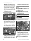
Starting the Engine
Follow starting procedures displayed at the gearshift lever
and as noted below.
Section 4: Operating Instructions
!
DANGER
Avoid injury or death from entanglement in the rotating
components and pinch points. All shields must be in place and
secure when operating. Keep all persons away from rotating
components and pinch points.
1. Set park brake.
2. Place gearshift in neutral. Depress clutch pedal.
Engine will not start with clutch pedal out.
3. Apply choke fully when engine is cold.
4. Turn ignition key fully clockwise and hold until engine
starts.
5. Release ignition key to run position and choke to
normal operating position immediately after engine
starts.
6. Turn ignition key counterclockwise to stop engine.
Operating a Gondo is like operating a car with a standard
transmission that has four or five speeds forward and one
reverse. The keyed 12 volt electronic ignition with a neutral
start and clutch depressed feature makes for safe and
easy starting.
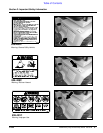
Braking is accomplished by simply depressing the
automotive style brake pedal located on the floorboard.
This activates both front and rear automotive type
hydraulic drum brakes. Depress clutch and brake pedals
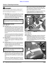
when coming to a complete stop. A lever action parking
brake is mounted on the floor board between operator and
passenger seats. Push the lever forward to the horizontal
position to engage the park brake and pull back to the
vertical position to release.
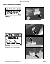
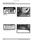
Raise cargo box by pulling back and holding on the dump
lever. Push forward on the lever and hold to lower the
cargo box. Stop cargo box movement by releasing the
lever.
!
DANGER
Make sure area behind cargo box is clear of personnel before
operating the dump lever. Bodily harm can result from being
pinched between the cargo box and another object or from a
load dumping and/or rolling onto a bystander.
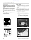
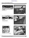
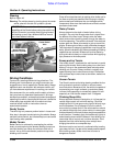
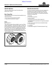
Dashboard Switches and Instruments
Refer to Figure 4-1A and Figure 4-1B on page 15
#1 Light Switch: Turns on two sealed beam head lights
when the switch key is on. Press top of light switch to
turn on lights and bottom of switch to turn off lights.
#2 Auxiliary Switch Slot: A 12 volt on/off accessory
switch may be installed at this location to operate an
auxiliary accessory such as a power winch.