


WIRING DIAGRAM 105
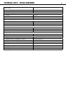
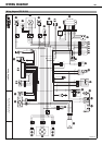
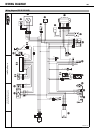
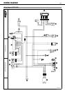
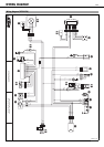
Components
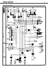
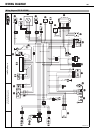
1 Battery
2 Generator
3 Ignition coil
4 Pulse generator
5 Voltage regulator/rectifier
6 Electric starter button
7 Starter relay with fuse
8 Starter motor
9 Emergency OFF switch
10 Throttle valve sensor TPS
11 Ignition curve plug connection
12 CDI controller
13 Headlight
14 Parking light
15 Brake / tail light
16 Light switch
17 Flasher switch
18 Flasher relay
19 Left front flasher
20 Left rear flasher
21 Right front flasher
22 Right rear flasher
23 Speedometer
24 Wheel speed sensor
25 Tripmaster switch (optional)
26 Horn button
27 Horn
28 Ignition switch
29 Front brake light switch
30 Rear brake light switch
31 High beam indicator light
32 Flasher indicator light
33 Plug connector for radiator fan (optional)
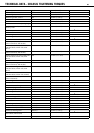
Cable colors
bl black
bl-wh black-white
br brown
br-bl brown-black
bu blue
bu-wh blue-white
gn green
gn-wh green-white
gr gray
or orange
pu violet
re red
re-bl red-black
re-wh red-white
wh white
wh-gn white-green
wh-re white-red