ENGLISH
20
Check chain tension
Jack the motorcycle up on its frame so that the rear wheel no longer touches
the ground.
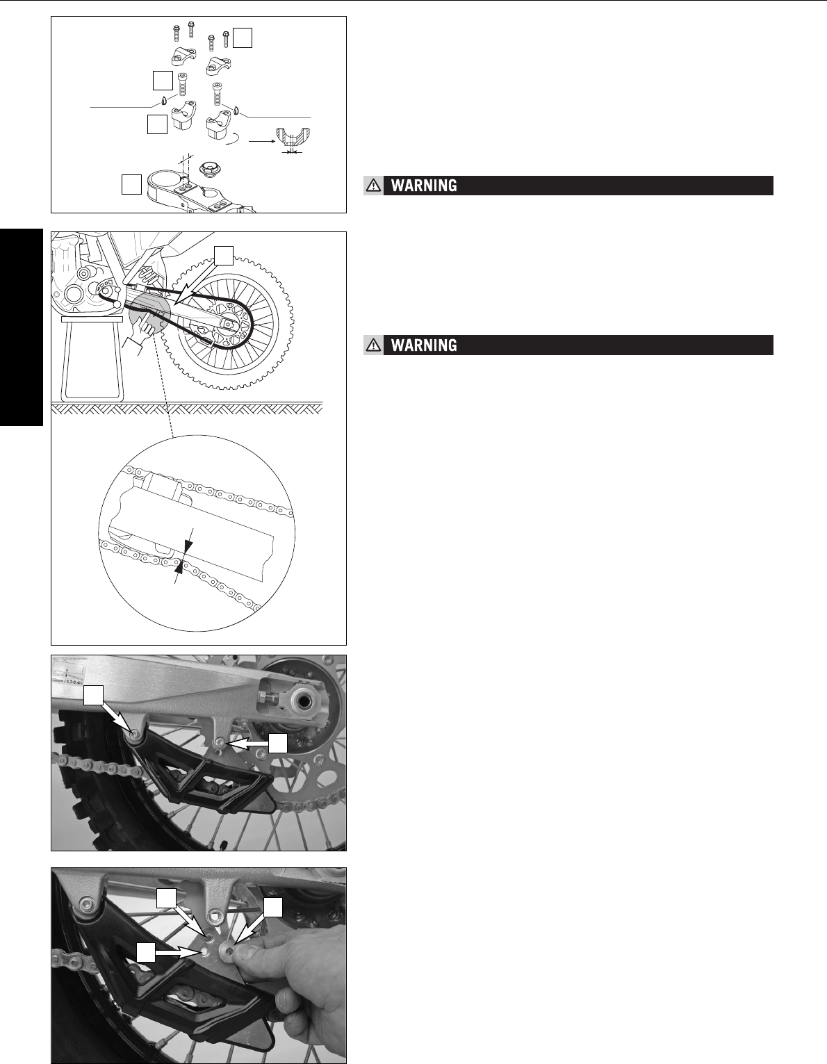
Press the chain upward at the end of the chain sliding component. The dis-
tance between the chain and the swing arm should be approx. 8 - 10 mm
(0.31 - 0.39 in). In the course of this procedure, the upper chain portion [A]
must be taut (see drawing). If necessary, correct the chain tension.
– If the chain tension is too great, parts within the secondary transmission
(chain, chain wheels and rear wheel bearings) will be subjected to unnec-
essary stress, resulting in premature wear and even chain breakage.
– Too much slack in the chain, on the other hand, can result in the chain
jumping off the chain wheels. If this happens, the chain could also block
the rear wheel or damage the engine.
– In either case the operator is likely to lose control of the motorcycle.
MAINTENANCE WORK ON CHASSIS AND ENGINE »
The upper triple clamp [1] includes 2 bores arranged at a distance of 15 mm
(0.6 in) from one another. The bores at the handlebar support [2] are offset
from the center by 3.5 mm (0.13 in). Accordingly, you can mount the han-
dlebar in 4 different positions.
For this purpose, remove screws [3] of the handlebar clamps and screws [4]
of the handlebar support. Position the handlebar support, and tighten screws
[4] to 40 Nm (30 ft.lbs). Mount the handlebar and handlebar clamps, and
tighten screws [3] to 20 Nm (15 ft.lbs). The gap between the handlebar sup-
port and the handlebar clamps should be the same size in the front and in
the rear.
The screws [4] must be secured with loctite 243.
Adapting the chain guide to the number of rear sprocket teeth
NOTE:
The position of the chain guide must be adjusted due to the large number of
rear sprockets available. Up to 44 teeth, insert the retaining screw on the
chain guide in the lower hole [C], from 45 teeth in the upper hole [D].
Loosen the screw [5] and remove screw [6]. Tilt the chain guide down and
insert the collard bush [7] in the respective hole.
Tighten the screws to 10 Nm.
LOCTITE 243
LOCTITE 243
15 mm
3.5 mm
1
2
3
4
8-10 mm / 0.3-0.4 in
A
B
C
5
6
7


