8.18
Section 8
Electrical System and Components
4. Apply a small amount of oil to the bearing in the
drive end cap, and install the armature with the
drive pinion.
5. Lubricate the fork end and center pivot of the
drive lever with drive lubricant (Kohler Part No.
52 357 02-S). Position the fork end into the space
between the captured washer and the rear of the
pinion.
6. Slide the armature into the drive end cap, and at
the same time seat the drive lever into the
housing.
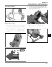
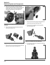
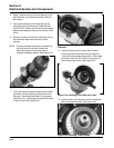
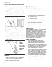
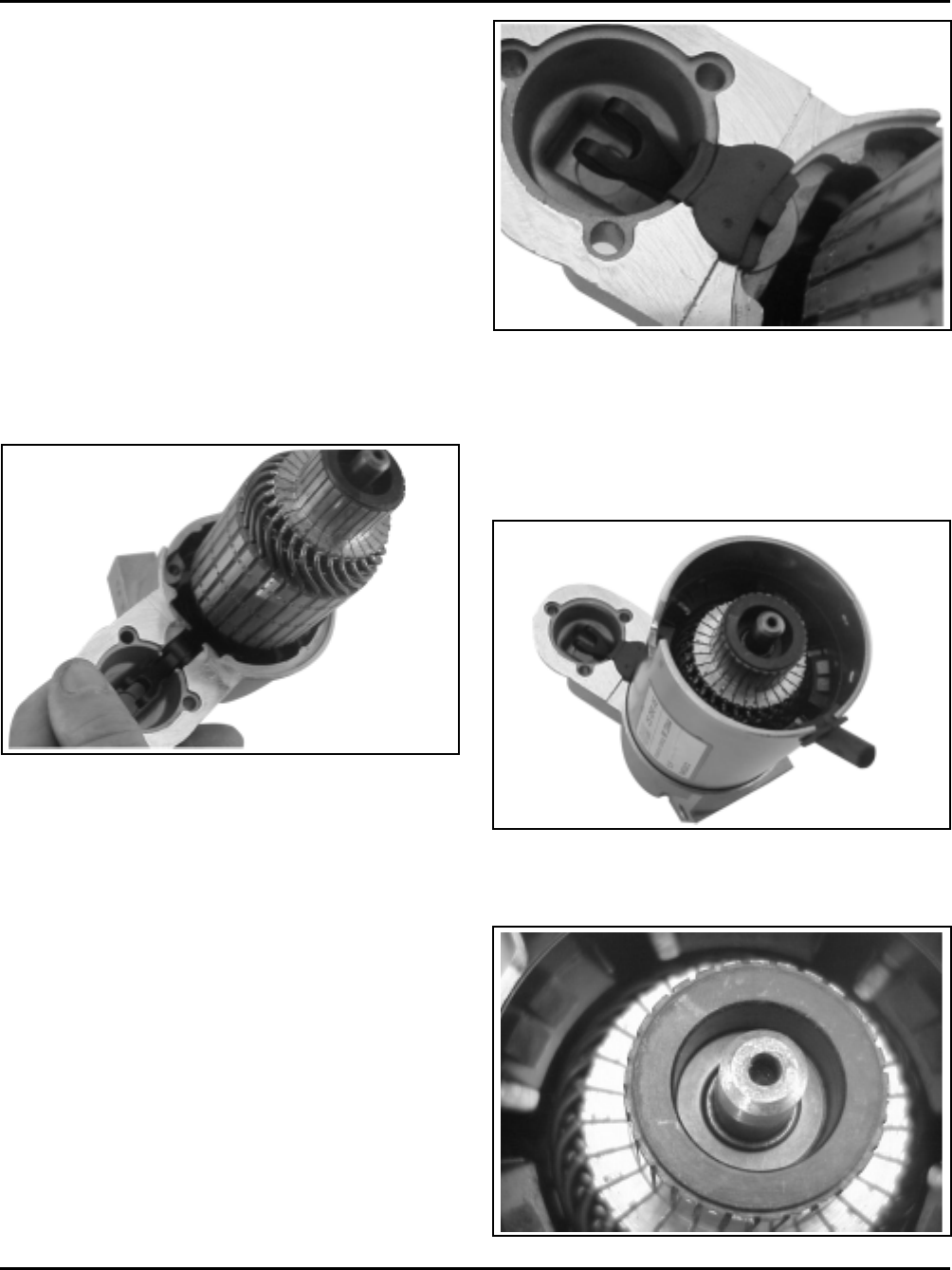
NOTE: Correctly installed, the center pivot section of
the drive lever will be flush or below the
machined surface of the housing which
receives the backup washer. See Figure 8-31.
Figure 8-31. Installing Armature and Pivot Lever.
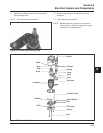
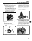
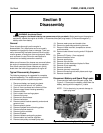
7. Install the backup washer followed by the rubber
grommet, into the matching recess of the drive
end cap. The molded recesses in the grommet
should be “out”, matching and aligned with those
in the end cap. See Figure 8-32.
Figure 8-32. Installing Backup Washer and
Grommet.
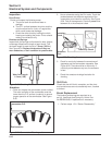
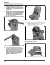
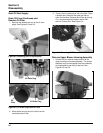
8. Install the frame with the small notch forward,
onto the armature and drive end cap. Align the
notch with the corresponding section in the rubber
grommet. Install the drain tube in rear cutout, if it
was removed previously. See Figure 8-33.
Figure 8-33. Installing Frame and Drain Tube.
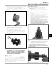
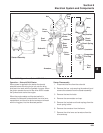
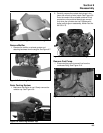
9. Install the flat thrust washer onto the commutator
end of the armature shaft. See Figure 8-34.
Figure 8-34. Installing Thrust Washer.


