


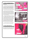
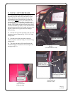
Fig. 9.1
(view from passenger’s side)
Rev. G
p. 7 of 9
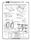
9. INSTALL ROOF
Note: Use a Phillips head screw driver to punch a hole
through the headliner at eight (8) bolt hole locations.
Punch holes from the inside out to avoid having the
headliner pull away from its glued surface.
9.1 Position the roof so that the row of five holes
lines up with the row of five holes in the windshield
support per Fig. 9.1. Install 3/4” long carriage bolts in
all roof holes except the two front corners. The left and
right front corner holes will require 1” long carriage
bolts. Locknuts to be on the inside of the cab. Plastic
washers to be under the bolt heads which are to be on
the exterior surface of the roof.
10. TIGHTEN ALL BOLTS
10.1 Push bottom portion of side frames tight against
the vehicle and tighten all bolts (including the four
large cab bar bolts that were loosened in step 2.1.
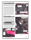
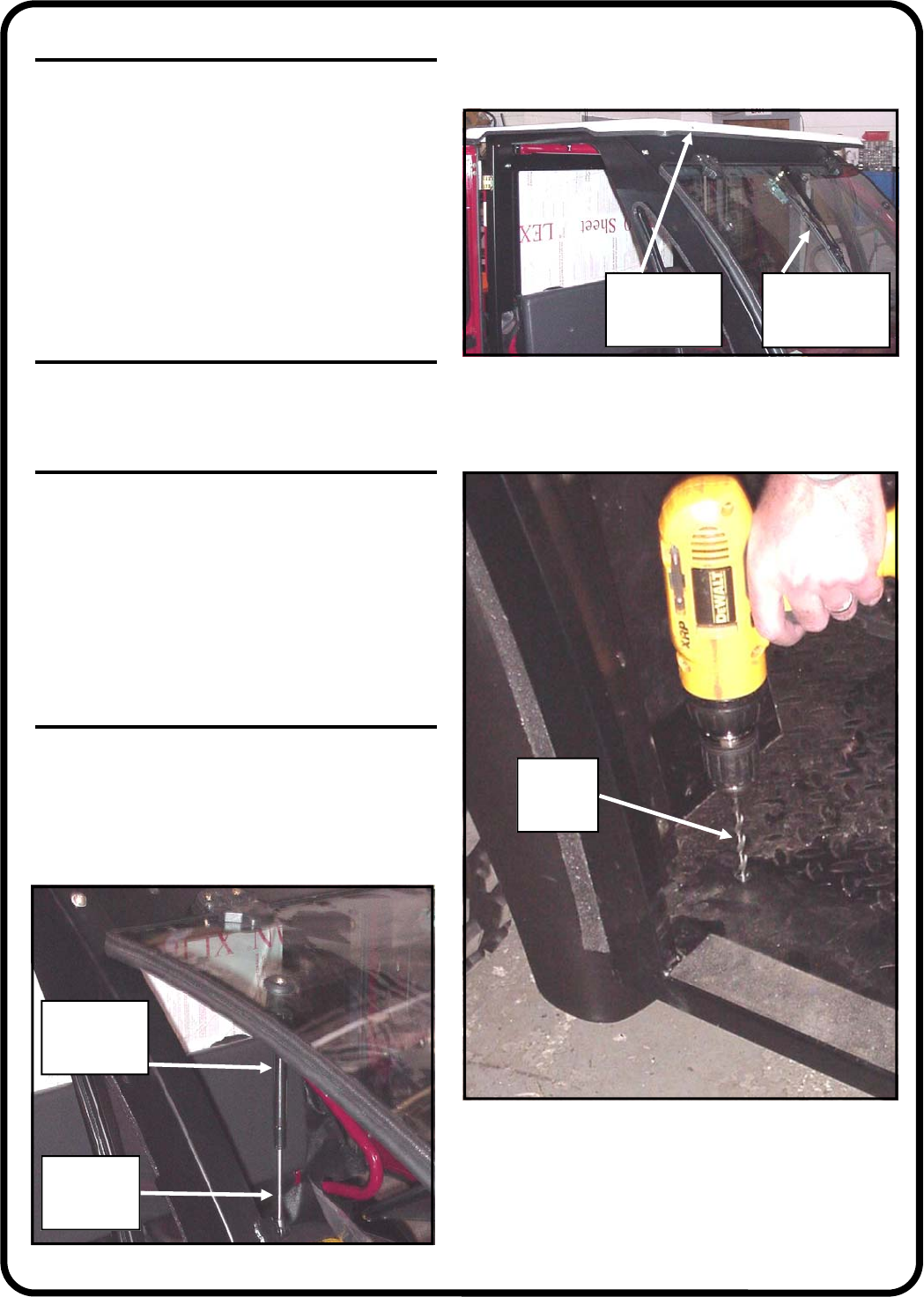
11. SECURE FLOORBOARDS
11.1 Before drilling, make sure the bottom portion of
the side frames are tight against the vehicle.
11.2 Drill an 11/32” diameter hole through the vehicle
floorboards using the square holes in the side frame
floorboard as guides per Fig. 11.2. A total of four holes
will need to be drilled (two per side).
11.3 Install 3/4” long carriage bolts in these newly
drilled out holes. Locknuts to be underneath the vehi-
cle.
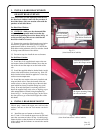
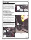
12. INSTALL GAS SHOCKS
12.1 With all bolts tight and floorboards drilled and
secured, open the windshield and attach the two gas
shocks as shown in Fig. 12.1. The rod end of the gas
shock must be installed down as shown. Press the but-
ton on the compression fastener to lock the gas shock
to the ball stud.
ref.: holes for
optional work
lights
ref.: shown with
optional wind-
shield wiper
small piston
end of gas
shock
large canister
end of gas
shock
Fig. 12.1 (view from passenger’s side)
Fig. 11.2
(view from driver’s side)
11/32”
diameter
drill bit