


Jaguar S
-
TYPE 2002.5
8
DATE OF ISSUE: March 2002 (PROVISIONAL)
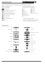
Symbols and Codes
Grounds
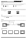
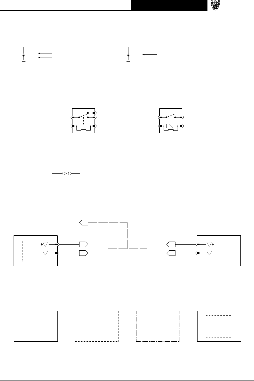
On figures where LHD and RHD circuits are combined and the ground designation differs from LHD to RHD, the RHD ground code is shown
in parentheses. If the ground designation is the same for LHD and RHD, only one ground code is used, with no parentheses.
EXAMPLE:
CA154
(CA141)
CA154
LHD Vehicles
RHD Vehicles
Same for LHD and RHD Vehicles
Relays
All relays are located in the Front and Rear Power Distribution Boxes and the Primary Junction Fuse Box. Relays do not have a separate relay
connector (base). All relays use the ISO pin numbering system (1, 2, 3, 4, 5). Each relay is identified by an “R” number unique only to the
fuse box in which it is located.
EXAMPLE:
3
1
5
2
R6
4
3
1
5
2
R2
CHANGE-OVER RELAY NORMALLY OPEN RELAY
Fuses
All fuses are located in the Front and Rear Power Distribution Boxes and the Primary Junction Fuse Box. Each fuse is identified by an
“F” number unique only to the fuse box in which it is located.
EXAMPLE:
F19 15A
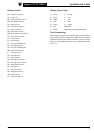
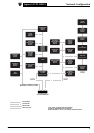
Networks
In most instances, networks are shown as a broken grey line to indicate that there is network communication between the depicted control
modules. Refer to Figures 20.1, 20.2, 20.3, 20.4 and 20.5 for circuit details.
EXAMPLE:
S
S
IP5-2
IP5-1
20.2
20.2 20.2
IP10-1
IP10-2
S
S
U
Y
U
Y
20.2
SCP
MESSAGE(S)
MESSAGE(S)
MESSAGE(S)
MESSAGE(S)
CONTROL MODULE CONTROL MODULE
Component Depictions
EXAMPLE:
COMPLETE COMPONENTS
AND CONTROL MODULES
INCOMPLETE COMPONENTS
(EXCEPT CONTROL MODULES)
ASSEMBLIES AND
POWER DISTRIBUTION FUSE BOXES
COMPONENTS WITH
INTERNAL ELECTRONIC CIRCUIT