


670042 (en) Page 3 of 8
y
Viton® is a registered trademark of the DuPont Company
y
Loctite® and 242® are registered trademarks of Henkel Loctite Corporation
y
y
Lubriplate® is a registered trademark of Lubriplate Division (Fiske Brothers Re ning Company)
y
ARO® is a registered trademark of Ingersoll-Rand Company
y
ply, but also by the material supply available at the inlet. The
material supply tubing should not be too small or restrictive.
Be sure not to use hose which might collapse.
When the diaphragm pump is used in a forced-feed ( ooded
inlet) situation, it is recommended that a “check valve” be in-
stalled at the air inlet.
Secure the diaphragm pump legs to a suitable surface to insure
against damage by vibration.
MAINTENANCE
Certain ARO “Smart Parts” are indicated which should be avail-
able for fast repair and reduction of down time.
Provide a clean work surface to protect sensitive internal mov-
ing parts from contamination from dirt and foreign matter dur-
ing service disassembly and reassembly.
Keep good records of service activity and include the pump in
preventive maintenance program.
Service kits are available to service two separate diaphragm
pump functions: 1. AIR SECTION, 2. FLUID SECTION. The Fluid
Section is divided further to match typical active Material Op-
tions.
Before disassembling, empty captured material in the outlet
manifold by turning the pump upside down to drain material
from the pump.
DIAPHRAGM PUMP SERVICE
GENERAL SERVICE NOTES:
Inspect and replace old parts with new parts as necessary. Look
for deep scratches on metallic surfaces, and nicks or cuts in “O”
rings.
Tools needed to complete disassembly and repair:
7/8” socket or wrench, 1/2” socket or wrench, 3/8” socket or
wrench, 3/8” Allen wrench, 10 mm Allen wrench, T-10 Torx
screwdriver, torque wrench (measuring inch pounds), “O”
ring pick.
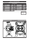
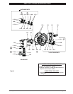
FLUID SECTION DISASSEMBLY
Remove (61) top manifold.
Remove (19) “O” rings, (21) seats, (12) washers and (22) balls.
Remove (60) bottom manifold.
Remove (19) “O” rings, (21) seats, (12) washers and (22) balls.
Remove (15) uid caps.
Remove (14) bolt, (6) diaphragm washer, (7) diaphragms and (5)
washer.
Remove (1) connecting rod from air motor.
Carefully remove remaining (14) bolt, (6) diaphragm washer, (7)
diaphragm and (5) washer from (1) connecting rod. Do not mar
surface of connecting rod.
FLUID SECTION REASSEMBLY
Reassemble in reverse order.
Lubricate (1) connecting rod with Lubriplate® or equivalent “O”
ring lubricant.
Connecting rod (1) should be installed using 96571 bullet, in-
cluded in service kit.
Install (5) washers with i.d. chamfer toward diaphragm.
y
y
y
y
y
y
y
y
y
y
1.
2.
3.
4.
5.
6.
7.
8.
y
y
y
y
GENERAL DESCRIPTION
The ARO U.L. listed pump for pumping petroleum products, o ers
high volume delivery at low air pressures and easy self-priming.
This model is designed specifically for transfer, bulk un-loading
or fueling applications. It includes a pressure relief valve (per U. L.
Speci cation 79) which restricts the uid outlet pressure to under
50 p.s.i. (3.4 bar). The relief valve must be plumbed to return the
bleed o fuel to the storage container.
Air operated double diaphragm pumps utilize a pressure di eren-
tial in the air chambers to alternately create suction and positive
fluid pressure in the fluid chambers, ball checks insure a positive
ow of uid.
Pump cycling will begin as air pressure is applied and it will con-
tinue to pump and keep up with the demand. It will build and
maintain line pressure and will stop cycling once maximum line
pressure is reached (dispensing device closed) and will resume
pumping as needed.
AIR AND LUBE REQUIREMENTS
WARNING
EXCESSIVE AIR PRESSURE. Can cause pump dam-
age, personal injury or property damage. The air supply
must be limited to 50 p.s.i.g. (3.4 bar) maximum inlet air
pressure.
A lter capable of ltering out particles larger than 50 microns
should be used on the air supply. There is no lubrication re-
quired other than the “O” ring lubricant which is applied during
assembly or repair.
If lubricated air is present, make sure that it is compatible with
the “O” rings and seals in the air motor section of the pump.
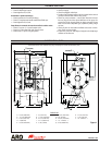
INSTALLATION
IMPORTANT
Requirements for the installation are included in the Flam-
mable and Combustible Liquids Code, NFPA No. 30, Automo-
tive and Marine Service Station Code, NFPA No. 30A and the
National Electric Code, ANSI / NFPA No. 70.
A fluid return hose which is compatible with the fluid being
pumped must be installed to the relief valve on the outlet
manifold to return uid back to the supply tank or pump inlet.
The pump must be grounded to prevent static discharge.
Grounding may be accomplished through the legs or to the
ground lug provided on the pump.
OPERATING INSTRUCTIONS
The pump should never be operated at pressures exceeding 50
p.s.i.g. (345 kPa) inlet air pressure. This pump is equipped with a
pressure relief valve on the material outlet manifold which will
open at 40 +/-4 p.s.i. (2.76 bar) to relieve pressure increases in
the outlet hoses / plumbing caused by thermal expansion or
other external forces.
Always ush the pump with a solvent compatible with the ma-
terial being pumped if the material being pumped is subject to
“setting up” when not in use for a period of time.
Disconnect the air supply from the pump if it is to be inactive
for a few hours.
The outlet material volume is governed not only by the air sup-
y
y
y
y
y
y
y
y
y