


Page 14
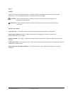
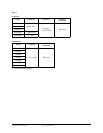
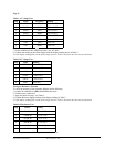
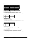
Table 5 AC mA Test:
Step Source Frequency Reading
1 58.00mA 50Hz 56.93 to 59.07
2 58.00mA 500Hz 56.93 to 59.07
3 580.0mA 50Hz 569.3 to 590.7
4 580.0mA 500Hz 569.3 to 590.7
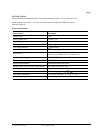
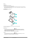
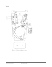
6. Turn the rotary switch to mA
.
7. Apply the inputs for steps 1-2 in Table 6.
8. For each input, compare the reading on the meter display to the reading in Table 6.
9. If the display reading falls outside of the range shown in Table 6, the meter does not meet specification.
Table 6 DC Current Test:
Step Source Reading
1 58.00mA 57.40 to 58.60
2 580.0mA 574.0 to 586.0
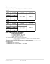
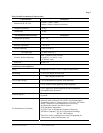
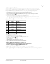
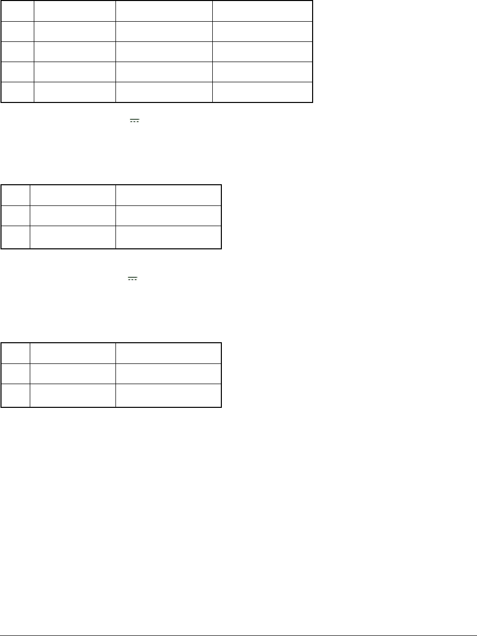
Testing the microamp Function
1. Turn the rotary switch to µA .
2. Apply the inputs for steps 1-2 in Table 7.
3. For each input, compare the reading on the meter display to the reading for your meter in Table 7.
4. If the display reading falls outside of the range shown in Table 7, the meter does not meet specification.
Table 7 DC µA Test:
Step Source Reading
1 580µA 574.0 to 586.0
2 5800µA 5740 to 5860
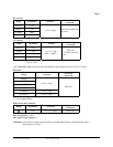
Testing the Frequency Function
To verify the accuracy of the meter’s frequency function, do the following:
1. Connect the calibrator to the VΩ and COM inputs on the meter.
Note: The accuracy of the calibrator’s frequency function must be appropriate for the specified
accuracy of the meter.
2. Set the rotary switch to Hz.
3. Set the function generator for the square wave voltage and frequency for steps 1-5 of Table 8.
4. Compare the reading on the meter display with the display reading shown in Table 8.
5. If the display reading falls outside of the range shown in Table 8, the meter does not meet specification.
Form number TM61320-2-4 Rev 2 September 2002