


Page 12
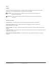
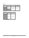
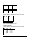
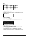
Table 1 AC Voltage Test:
Step Input Frequency Reading
1 5.800V 50Hz 5.743 to 5.857
2 5.800V 500Hz 5.743 to 5.857
3 58.00V 50Hz 57.43 to 58.57
4 58.00V 500Hz 57.43 to 58.57
5 580.0V 50Hz 574.3 to 585.7
6 580.0V 500Hz 574.3 to 585.7
7 750V 50Hz 738 to 762
8 750V 500Hz 738 to 762
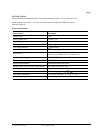
6. Turn the rotary switch to “V ” position.
7. Set the calibrator for the voltage from step 1 to 6 in Table 2.
8. Compare the reading on the meter display with the display reading shown in Table 2.
9. If the display reading falls outside of the range shown in Table 2, the meter does not meet specification.
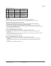
Table 2 DC Voltage Test:
Step Input Reading
1 580.0mV 576.9 to 583.1
2 -580.0mV –576.9 to –583.1
3 5.800V 5.769 to 5.831
4 58.00V 57.69 to 58.31
5 580.0V 576.9 to 583.1
6 900V 894 to 906
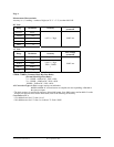
Testing the Resistance Function
To verify the accuracy of the resistance function, do the following:
1. Connect the calibrator to VΩHz and COM on the meter.
2. Turn the rotary switch to Ω.
3. Apply the inputs for step 1-6 in Table 3.
4. Compare the meter display readings to the display readings in Table 3.
5. If the display reading falls outside of the range shown in Table 3, the meter does not meet specification.
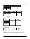
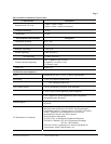
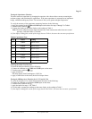
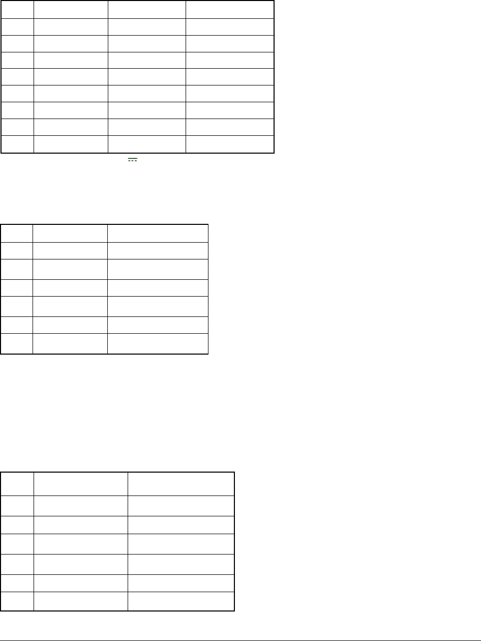
Table 3 Ω Resistance Test:
Step Source Reading
1 580.0 Ω 575.7 to 584.3
2 5.800K Ω 5.757 to 5.843
3 58.00K Ω 57.57 to 58.43
4 580.0K Ω 575.7 to 584.3
5 5.800M Ω 5.740 to 5.860
6 58.00M Ω 57.11 to 58.59
* Lead resistance on the 400Ω range is not included in error.
Form number TM61320-2-4 Rev 2 September 2002