


Controls and Indicators
2005 Husqvarna 4210-G, 4210-E, 4210-GXP, and 4210-EXP Owner’s Manual Page 17
• The warning light will not illuminate if the charge is 90% or more complete. The onboard computer will
retain in memory the amount of charge needed to fully replenish the batteries and will complete the
charge during the next charge cycle.
• When the charger is unplugged, the warning light will illuminate and remain illuminated for 10 seconds
if the charge is less than 90% complete but the vehicle has enough power for approximately 30 min-
utes of operation. This will alert the operator that the vehicle may be used, but that it must be charged
to completion as soon as possible.
• The warning light will repeatedly illuminate for 10 seconds, with 4 second intervals if the charger times
out at 16 hours and the batteries are not sufficiently charged. See the battery charger owner’s man-
ual. This indicates an abnormal charge cycle. The charger and batteries should be checked by your
Husqvarna distributor/dealer.
• The warning light will repeatedly illuminate for 10 seconds, with 4 second intervals during a charge
cycle (DC plug is still connected) if AC power to the charger is interrupted. The light will go out when
AC power is restored.
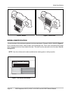
LED Light: In addition to the warning light, there is an infrared LED in the dash light assembly, which trans-
mits an infrared signal from the onboard computer (OBC). This signal is received by the optional Communi-
cation Display Module (Husqvarna 603 00 18-63), which provides information on the condition of the vehicle
and batteries.
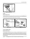
TOW/RUN SWITCH
Electric Vehicles Only
ý WARNING
• Place Tow/Run switch in the TOW position before disconnecting or connecting the batteries.
Failure to heed this warning could result in a battery explosion or severe personal injury.
• When the Tow/Run switch is in the TOW position, all motor braking functions, including zero
speed detect, are disabled.
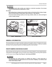
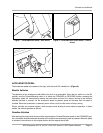
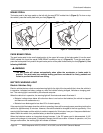
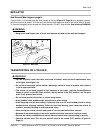
Electric vehicles are equipped with a Tow/Run switch, located under the seat just above the Forward/Reverse
switch (Figure 12). The switch must be in the RUN position in order to operate the vehicle. When the switch
is in the TOW position, power to the vehicle electrical components is turned off and the vehicle will not oper-
ate. See following NOTE.
NOTE: After placing the Tow/Run switch in the TOW position, allow 10 seconds to elapse before switching
back to the RUN position.
After placing the Tow/Run switch in the RUN position, allow 10 seconds to elapse before operating
the vehicle.
The Tow/Run switch should be placed in the TOW position under the following conditions:
• Before Towing the Vehicle: Place the Tow/Run switch in the TOW position to disable all motor braking
functions, thus preventing possible damage that could occur to the vehicle or electrical components if
the vehicle is towed while the zero speed detect motor braking function is operating.
• Before Disconnecting or Connecting Battery Cables: Place the Tow/Run switch in the TOW posi-
tion to turn off power to the vehicle electrical system, thus preventing severe arcing and possible bat-
tery explosion as the battery cables are disconnected.
• For Long Term Storage: Place the Tow/Run switch in the TOW position to turn off power to the vehicle
electrical system, thus preventing vehicle electrical components from discharging the batteries.