


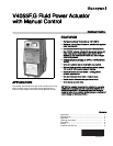
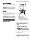
V4055F,G FLUID POWER ACTUATOR WITH MANUAL CONTROL
65-0029-02 6
1. Turn off the gas supply at the manual shutoff valve
located upstream from the valve(s) being serviced.
2. Shut off all electrical power to the valve actuator(s).
3. Mark and disconnect the wires from the actuator termi-
nals. Remove conduit and disengage the damper linkage
assembly (if applicable.
4. Loosen the two set screws from the valve to lift off the
actuator.
5. If the actuator is to be replaced and it did not leak
hydraulic fluid, skip to Step 11.
NOTE: It is good practice to inspect the inside of the
valve whenever the actuator is replaced. To do
so, remove the bonnet assembly, inspect the
valve and bonnet. If all is well, proceed to Step
7.
6. If the actuator leaked hydraulic fluid onto the valve (the
fluid is red), it must be cleaned off from the valve and
bonnet assembly.
a. Wipe off the outer valve body.
b. Remove the valve bonnet bolts and lift off the bonnet.
NOTE: V5055/V5097C and E Valves have additional
internal springs that will push the bonnet up as
the bolts are loosened.
c. Inspect the inside of the valve.
IMPORTANT
If fluid is present on the inside surfaces of the valve
body or bonnet surfaces, the bonnet assembly or
entire valve must be replaced. See Table 3 below for
the bonnet assembly part number.
d. If the inside surfaces are clear of hydraulic fluid,
clean the bonnet assembly and be sure to remove all
hydraulic fluid from the inside and outside of the
actuator mounting curb. This is the “cup-like” area
around the valve stem. Avoid using a cleaning solu-
tion as it may damage the rubber seals used in the
valve.
7. If the valve bonnet assembly is in good condition and is
not replaced, replace the bonnet seal. Do not reuse the
old bonnet seal. See Table 4 below for the seal number.
8. Coat seals with grease provided and position in valve
body/bonnet assembly.
9. Carefully seat the bonnet assembly on the valve body.
Be sure the seals are in their proper position. On those
valves with a spring below the disc, be sure the spring is
centered in the indentation on the inside of the valve
body.
10. After positioning the bonnet assembly, replace the
screws removed earlier.
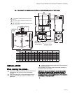
NOTE: When replacing the bonnet assembly on the 4-
inch valve, draw it evenly into the valve body.
Finger-tighten the eight bolts. Draw the bonnet
assembly into the valve by tightening, in order,
bolts 1, 5, 7 and 3 (two turns each). Repeat until
the bonnet assembly is seated. Tighten the
remaining bolts. Torque the bolts as
follows:
11. Remount the actuator on the bonnet assembly. Tighten
the two set screws (50-60 inch pounds.
12. Replace the damper crank arm assembly.
13. Re-attach the wires removed from the actuator terminals
and turn on the electrical power.
14. With the gas still off, cycle the actuator to check for
proper mechanical operation.
CAUTION
Be sure to perform a bonnet seal and seat leak check
after installation.
Be sure to read and follow all instructions that come
with the actuators, valves, seal and bonnet kits.
**Each replacement assembly contains the bonnet assembly,
two rubber seals, and a tube of grease. It must be used only on
the type of valve indicated above.
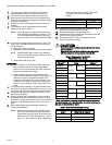
Valve Size Torque
3/4 in. (19 mm) to 1-1/2 in. (38 mm) 55 in.-lb.
2 in. (51 mm) to 4 in. (102 mm) 75 in.-lb.
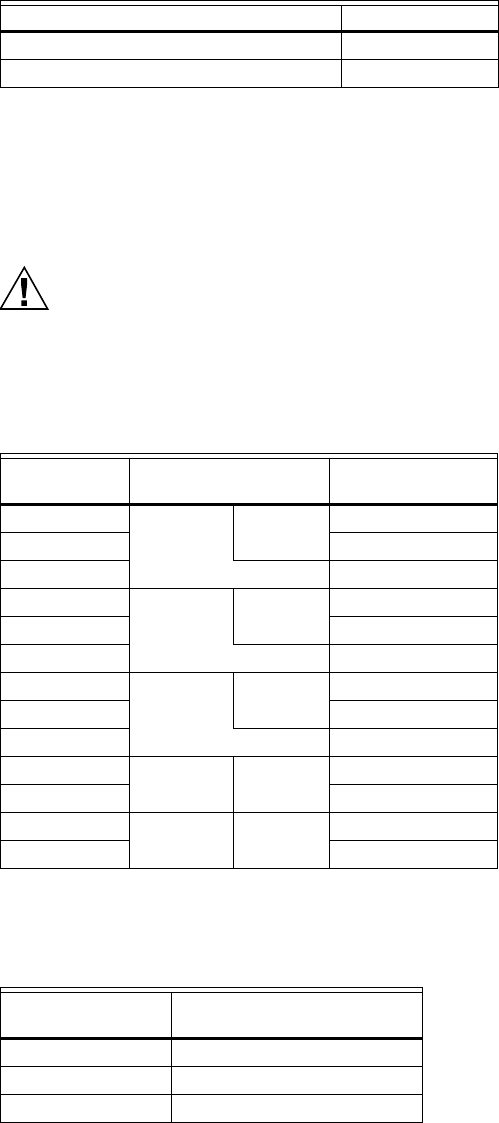
Table 3. Replacement Bonnets for
V5055/V5097 Gas Valves.
Replacement
Bonnet** Valve
Valve Size (in
inches.)
133398AA V5055A V5097A 3/4, 1, 1-1/4, 1-1/2
133417AA 2, 2-1/2, 3
Not Available (On-Off) 4
133398BA V5055B V5097B 3/4, 1, 1-1/4, 1-1/2
133417BA 2, 2-1/2, 3
Not Available (Characterized Guide) 4
133398CA V5055C V5097C 3/4, 1, 1-1/4, 1-1/2
133417CA 2, 2-1/2, 3
136911CA (Proof of Closure) 4
Not Available V5055D V5097D 3/4, 1, 1-1/4, 1-1/2
Not Available 2, 2-1/2, 3
136308BA V5055E V5097E 3/4, 1, 1-1/4, 1-1/2
Not Available 2, 2-1/2, 3
Table 4. Gas Valve Replacement Seals.
Replacement Seal
Assy # Valve Size (in inches.)
133393A 3/4, 1, 1-1/4, 1-1/2
133392A 2, 2-1/2, 3
137253A 4