


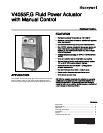

V4055F,G FLUID POWER ACTUATOR WITH MANUAL CONTROL
65-0029-02 4
CAUTION
Electrical Shock and Equipment Damage Hazard.
Can cause serious injury or death.
1. Disconnect power supply before making wiring
connections to prevent electrical shock and
equipment damage.
2. All wiring must comply with all applicable electrical
codes, ordinances and regulations. All wiring must
be NEC Class 1.
3. Voltage and frequency of the power supply
connected to this control must agree with those
marked on the device.
4. Maximum total connected load to both switches (if
used) must not exceed 1800 VA.
WARNING
Explosion Hazard.
Can cause explosion, serious injury or death.
1. Turn off gas supply before starting installation.
2. Disconnect power supply for valve actuator before
beginning installation.
3. Install the valve so the arrow on the valve body
points in the gas flow direction.
Install Valve
The actuator is mounted directly on the valve bonnet after the
valve is installed in the gas supply line. Refer to the instruction
sheet packed with the gas valve for details of installation. When
installing the valve, ensure that:
1. Sufficient clearance.is left for installation and service of
the actuator.
2. Ambient temperatures at the valve location will remain
within -40°F to +150°F (-40°C to +66°C).
Install Accessory Switches (If Needed)
A SPDT switch may be installed to operate an auxiliary load up
to 1/2 hp (0.37 kW). The switch may be adjusted to operate at
any point in the valve stroke.
A valve-closed indication switch may also be installed on any
V4055 actuator to provide a valve seal overtravel interlock
(valve-closed indication) when used with a V5055C or E valve
(with double seal).
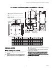
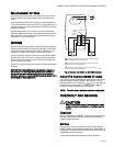
Fig. 2. V4055 actuator with cover removed.
NOTE: A V5055A, B or D valve can also be fitted with a bon-
net assembly with 2 seals to provide a valve seal
overtravel interlock.
The SPDT valve-closed indication switch is installed to make or
break a circuit when the valve is in the closed position. The
switch is not adjustable.
NOTE: Mark the actuator or valve to indicate any changes
made.
To install the switches, proceed as follows:
1. Remove the actuator faceplate (2 screws).
2. Remove the silver-colored barrier to expose the actuator
stem.
3. Insert the auxiliary switch in the position indicated in Fig.
2. Fasten with 2 screws through the actuator base.
4. Insert the valve-closed indication switch in the position
shown in Fig. 2. The valve-closed indication switch
mounts against the side of the actuator housing. The
mounting holes are spaced to mount the switch only in
the correct position. Fasten with 2 screws through the
actuator base.
5. If only 1 switch is used, install the narrow barrier included
with the switch in the unused space.
6. Mount the actuator before making wiring connections
and adjustments to the switch.
M23961A
133568
AUXILIARY
SWITCH
133569
VALVE-
CLOSED
INDICATION
SWITCH
EACH SWITCH SECURED
BY TWO SCREWS FROM
UNDERSIDE OF BASE
IF ONLY ONE SWITCH IS
USED, INSTALL BARRIER
IN OPEN POSITION
ADJUSTING SCREW
FOR AUXILIARY SWITCH