


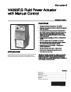


V4055F,G FLUID POWER ACTUATOR WITH MANUAL CONTROL
5 65-0029-02
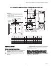
Mount Actuator On Valve
Check the final position of the valve body to be sure that the
actuator will be in the proper position when mounted on the
valve.
If two smaller size valves are mounted very close together, as
in an Industrial Risk Insurers (formerly F.I.A.) type valve train, it
may be necessary to mount the actuator “off center” to provide
adequate clearance.
Slip the bottom collar of the actuator over the valve bonnet
assembly. Rotate the actuator to the desired position and use a
5/32 inch Allen wrench to tighten the two setscrews securely
(50 to 60 Ib.-in. [5.7 to 6.8 N.m]).
WIRING
Disconnect power supply before making wiring connections to
prevent electrical shock and equipment damage. Wiring must
comply with all applicable electrical codes, ordinances, and
regulations. Wiring to the actuator must be NEC Class 1.
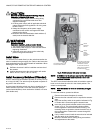
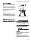
Connect the power supply to terminals 1 and 2 on the V4055
terminal strip. Refer to Fig. 3 for auxiliary switch connections.
For typical system hookups, refer to instructions packed with
device used to control valve.
When all wiring connections are complete, replace the actuator
faceplate.
NOTICE: Per Industry Standards, the actuator is required a
conduit seal or a cable type that is sealed be installed in a
device that can result in a flammable liquid flow through a
conduit or cable to an electrical ignition source in the event of a
seal leakage or diaphragm failure.
Fig. 3. External connections to the V4055 actuator.
Adjust The Auxiliary Switch (If Used)
The auxiliary switch is adjustable throughout the stroke of the
actuator. With the switch installed in the actuator, turn the
adjusting screw (Fig. 2) clockwise to cause the switch to
operate earlier in the stroke or counterclockwise to
cause the switch to operate later in the stroke.
NOTE: The valve-closed indication switch is not adjustable.
CHECKOUT AND SERVICE
CAUTION
Only a trained, experienced, flame safeguard control
service technician should check out and service this
control.
Checkout
After the installation is complete, cycle the valve several times
with the manual fuel shutoff cock closed before testing the
system in actual operation.
Service
The actuator is not field repairable, except for replacing the
auxiliary switch, valve-closed indication switch, and READY TO
OPEN light. See INSTALLATION section for procedure. Do not
disassemble the valve actuator.
If the actuator should fail to operate properly, replace it.
1
2
3
2
1
1
2
AUXILIARY
SWITCH
L1
HOT
L2
POWER SUPPLY. PROVIDE OVERLOAD PROTECTION AND
DISCONNECT MEANS AS REQUIRED.
SWITCH BETWEEN THESE TWO LEADS IS CLOSED WHEN
VALVE IS SHUT (DE-ENERGIZED).
3
SWITCH BETWEEN THESE TWO LEADS IS OPEN WHEN
VALVE IS SHUT (DE-ENERGIZED).
NO
NC
C
NO
NC
C
PROOF-OF-CLOSURE
SWITCH
2
3
M7334B