


ML6421, ML7421 NON-SPRING RETURN ELECTRIC LINEAR VALVE ACTUATORS
7 63-2515—4
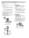
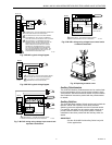
Actuator Override
To override the control signal (for freeze protection or similar
applications), connect the 24 Vac common (T2) to either
terminal O1 or O2. Connecting to terminal O1 fully extends
the actuator stem. Connecting to O2 fully retracts the actuator
stem.
The control signal (+) is ignored when the override signal is
applied to terminal O1 or O2. This override can be achieved
with a switch or a relay. See Fig. 12.
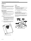
Direction of Action
The direction of action can be changed by repositioning the
selector plug W3.
Fig. 12. Connections for overriding control signal to drive
actuator to a specific position.
CHECKOUT
The actuator can be checked out either directly or using a controller.
Direct Checkout
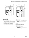
1. Mount the actuator for the required application.
2. Check the valve position and make sure that 24 Vac is
correctly applied to the actuator.
3. Apply the control signal to the appropriate leadwires to
move the valve in the required direction.
4. If the actuator does not move, make sure the actuator is
properly installed.
5. If the actuator is correctly installed and does not run,
replace the actuator.
Controller Checkout
1. Adjust the setpoint of the controller to call for opening or
closing the valve. Observe the actuator.
2. If the valve is closed, it should begin to open.
3. If the valve remains closed, move the setpoint further
toward the open setting.
4. If the valve does not move, check for 24 Vac in the
actuator power input.
5. If 24 Vac is present and the actuator does not operate,
reverse the controller leadwires to determine if the
device is incorrectly wired.
6. If wiring is correct, 24 Vac is present on the power input
terminals, and the actuator does not run, replace the
actuator.
POWER SUPPLY. PROVIDE DISCONNECT MEANS
AND OVERLOAD PROTECTION AS REQUIRED.
F
+
0-10Vdc OR 2-10 Vdc CONTROL SIGNAL. SEE SIGNAL
INPUT (+) SECTION.
SEE OVERRIDE SECTION FOR DETAILS ON
OVERRIDE OPERATION.
2-10 Vdc FEEDBACK SIGNAL. SEE OUTPUT SIGNAL
FEEDBACK SECTION.
ML7421
WIRING
STRIP
F
+
–
T2
T1
O1
O2
1
3
4
2
INPUT
(FEEDBACK)
OUTPUT
3
2
SP3T
OVERRIDE
SWITCH
4
1
L1
(HOT)
L2
–
M17438