


ML6421, ML7421 NON-SPRING RETURN ELECTRIC LINEAR VALVE ACTUATORS
63-2515—4 6
OPERATION
General
The drive of the actuator synchronous motor is converted into
the linear motion of the actuator stem by using a worm gear
transmission. A button retainer clip connects the actuator
stem to the valve stem.
The internal force sensor, using installed microswitches, turns
off the actuator when the specified stem force is reached.
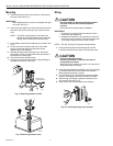
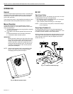
Manual Operation
The ML6421 and ML7421 are equipped with a manual
operator knob (see Fig. 10) to open or close the valve in the
event of power failure:
1. Turn off or disconnect the power supply before manually
operating the actuator.
2. Push down on the manual operator knob and turn the
knob:
a. Counterclockwise to drive the stem downward.
b. Clockwise to draw the stem upward.
IMPORTANT
Manual operation allows very high closing force that
can jam the actuator spindle, exceed the force switch
ratings, and stop the motor. After a manual valve
close-off operation, release the spindle one turn by
turning the manual operator knob. This will ensure
automatic disengagement of the manual operator
upon power resumption.
NOTE: If the manual operator knob is not pushed in while
turned, it will rotate only a short distance before
disengaging without power resumption.
Fig. 10. Manual operator knob.
ML7421
Signal Input Failure
Using selector plug W1, the actuator can be set to run to one
of three positions in event of a signal failure:
• 0%: Actuator position corresponds with 0 or 2 Vdc signal.
• 50%: Actuator stem in mid-position.
• 100%: Actuator position according to 10 Vdc signal.
NOTE: If W4 is set to the mA position, the actuator always
runs to 0 percent.
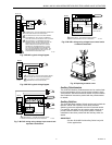
Output Signal Feedback (F)
An analog output signal (2 to 10 Vdc) that represents the
actual actuator stem position is available at Terminal F. It can
be used for remote indication of the stem position.
With the actuator stem fully down, the output signal is 10 Vdc.
The output of the signal does not change when the actuator
action reverses using W3 or W4 (see Signal Input Failure
section and Fig. 11).
Fig. 11. Location of selector plugs.
M6640
M17437
0-10V
(0-20mA)
2-10V
(4-20mA)
W2
10V (20mA)
0%
10V (20mA)
VmA
W4
W3
W1
100%50%