ML6421, ML7421 NON-SPRING RETURN ELECTRIC LINEAR VALVE ACTUATORS
5 63-2515—4
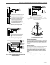
Fig. 5. ML6421 typical wiring diagram.
Fig. 6. ML7421 typical wiring diagram.
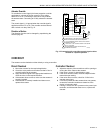
Fig. 7. ML7421 wiring using voltage input control and
separate transformers.
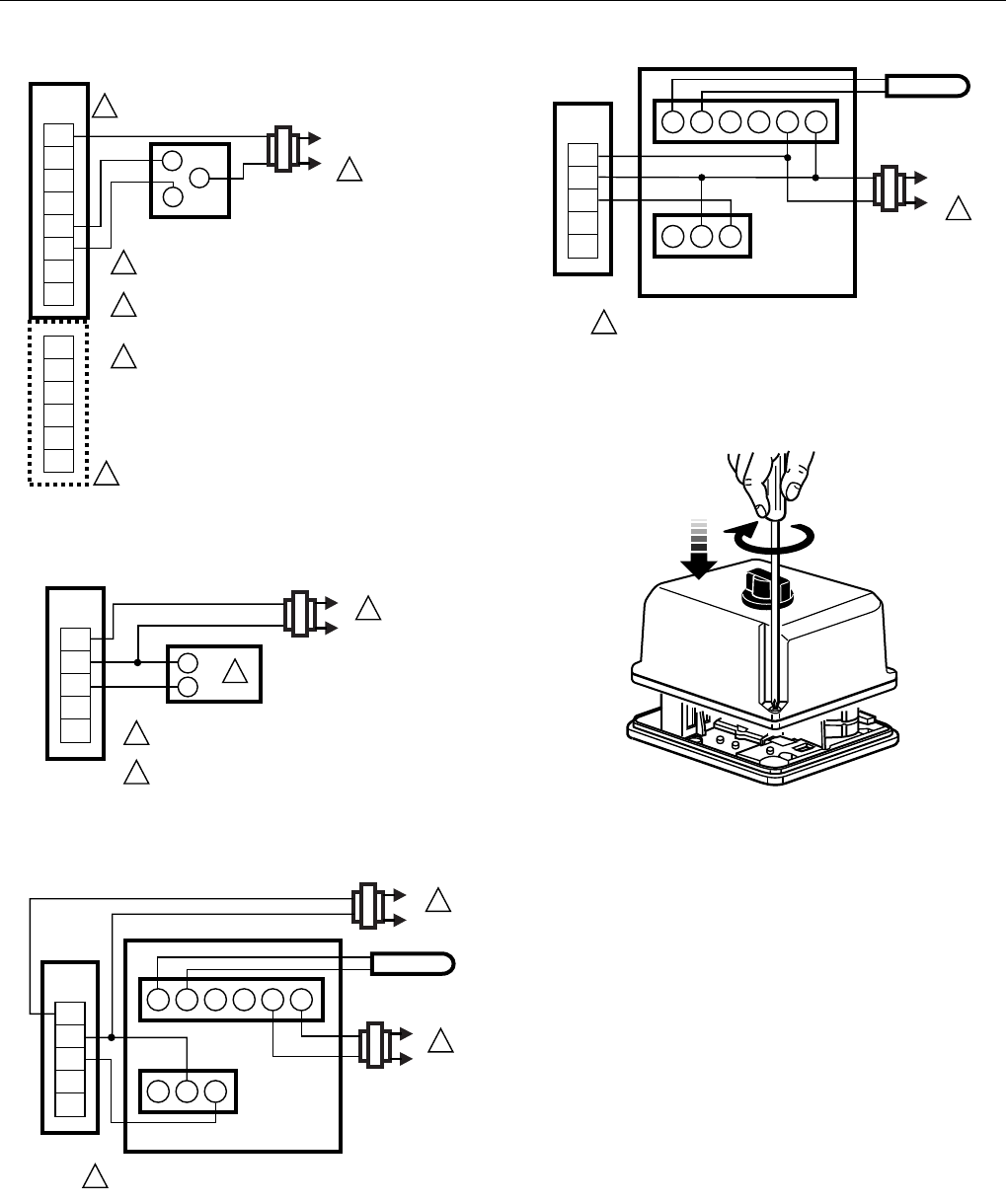
Fig. 8. ML7421 wiring using voltage input control and a
common transformer.
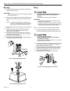
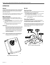
Fig. 9. Replacing actuator cover.
Auxiliary Potentiometers
The 43191679 Auxiliary Potentiometers can be used as feed-
back potentiometers and to provide remote indication of the
valve position. See the Accessories section for part numbers.
See Installation Instructions packed with the potentiometers
for details.
Auxiliary Switches
The 43191680 Dual Auxiliary Switch can be used on both the
ML6421 and ML7421 Electric Linear Valve Actuators.
Switching points are adjustable over the full actuator stroke.
For example, the switch can be used to switch pumps or to
provide remote indication of any stroke position. See the
Installation Instructions packed with the auxiliary switch for
details.
IMPORTANT
Use the 43191680 Dual Auxiliary Switch only with
24 Vac applications.
WIRING
STRIP
T1
T2
W
B
1
L1
(HOT)
L2
W
R
W
B
T
Y
G
R
B
SPDT
ML6421A,B
2
3
POWER SUPPLY. PROVIDE DISCONNET MEANS AND
OVERLOAD PROTECTION AS REQUIRED.
ALL WIRING BLOCKS HAVE THE SAME NUMBER
OF TERMINALS (8), BUT THE ONLY TERMINALS
THAT ARE ACTIVE ON THIS BLOCK ARE T1,W,AND B.
THE R-W-B AND T-Y-G TERMINALS ARE A SIX
TERMINAL WIRING BLOCK SEPARATE FROM THE
MAIN BLOCK. THEY DO NOT APPEAR ON ALL
MODELS BECAUSE R-W-B ARE FOR A SINGLE
FEEDBACK POTENTIOMETER AND T-Y-G ARE
FOR A SECOND FEEDBACK POTENTIOMETER
(BOTH POTENTIOMETERS ARE 220 OHMS). THE
REQUIRED WIRING BLOCKS ARE PART OF THE
POTENTIOMETER ACCESSORY KITS.
1
2
3
CONTROLLER
M17433
WIRING
STRIP
T1
+
T2
O1
O2
1
L1
L2
–
+
OUTPUT
2
POWER SUPPLY. PROVIDE DISCONNECT MEANS
AND OVERLOAD PROTECTION AS REQUIRED.
0 TO 10 OR 2 TO 10 VDC CONTROL SIGNAL
(DEPENDING ON ACTUATOR MODEL).
1
2
M17434A
ML7421
L1
L2
1
1
1
1
2
2
3
3
4
5
6
L1
L2
1
T775 (WITH 2 TO 10 VDC OUTPUT)
DUAL
TRANSFORMERS
SENSOR
POWER SUPPLY. PROVIDE DISCONNECT MEANS
AND OVERLOAD PROTECTION AS REQUIRED.
M17435A
WIRING
STRIP
T1
+
T2
O1
O2
ML7421
L1
(HOT)
L2
1
1
1
1
2
2
3
3
4
5
6
T775 (WITH 2 TO 10 VDC OUTPUT)
SINGLE
TRANSFORMER
SENSOR
POWER SUPPLY. PROVIDE DISCONNECT MEANS
AND OVERLOAD PROTECTION AS REQUIRED.
M17436A
40 VA, 24 VAC
WIRING
STRIP
T1
+
T2
O1
O2
ML7421
M17464


