


63-2511—1 G.R. Rev. 06-04 www.honeywell.com
Automation and Control Solutions
Honeywell International Inc. Honeywell Limited-Honeywell Limitée
1985 Douglas Drive North 35 Dynamic Drive
Golden Valley, MN 55422 Scarborough, Ontario
M1V 4Z9
ML6194, ML6294 NON-SPRING RETURN DIRECT COUPLED ACTUATORS
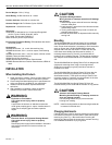
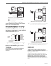
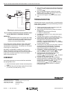
Fig. 13. Common transformer with one controller output
and two ML6194A,C or ML6294A,C Actuators.
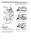
IMPORTANT
ML6194/ML6294 Actuators can operate with a DDC
Controller that emulates an spdt break-before-make
switch. Do not short-cycle actuator. Short-cycling
actuator can cause premature failure.
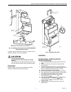
The actuator has a position indicator to show shaft position.
As the indicator moves with the shaft, it gives an angular
representation of shaft position. The indicator can be rotated
to show open or closed position.
ML6194D,F and ML6294D,F models provide a time-out
feature that removes power from actuator submotor if the
actuator receives the same signal or no call from controller for
longer than a nominal five minutes. This time-out feature
helps to extend actuator life.
CHECKOUT
Use following procedure to check out ML6194 and ML6294
Non-Spring Return DCA:
1. Check that actuator position indicator and shaft position
agree.
2. If actuator has a time-out feature, apply 24 Vac to black
(T1) and red (T2) leads (see Fig. 7 or 9).
3. Apply 24 Vac control signal to blue (B) lead with respect
to black (T1) lead. The actuator should drive shaft open
(clockwise ).
4. Apply 24 Vac control signal to yellow (W) lead with
respect to black (T1) lead. The actuator should drive
shaft closed (counterclockwise ).
5. If 24 Vac control signal is removed, actuator should
stop.
TROUBLESHOOTING
If actuator does not drive, travel full stroke, or operate properly
during checkout, perform following troubleshooting procedure
before replacing actuator:
1. Check actuator label to make sure proper power and
control signal requirements are met.
2. When actuator should be driving, check for 24 Vac at
actuator wires:
a. Black (T1) and yellow (W) or blue (B).
b. Black (T1) and red (T2).
3. If voltage is not present or is low, check power supply
and controller.
4. If actuator does not drive in correct direction when a
control signal is applied, reverse yellow and blue wires.
5. Remove power and fully depress and hold down
disengage button while trying to turn shaft
clockwise and counterclockwise . If shaft
turns freely through 90° stroke, and actuator is installed
correctly, replace actuator.
6. If shaft does not turn freely for full 90° stroke, check for
any binding and verify that actuator is loose on its
mounting bracket to prevent binding. If necessary,
adjust mounting bracket to prevent binding.
7. If no binding is present, remove actuator and turn shaft
clockwise and counterclockwise . If shaft
does not turn freely, repair or replace damper.
8. If shaft turns freely, fully depress and hold down
disengage button and turn actuator hub
clockwise and counterclockwise . If actuator
hub does not turn, replace actuator.
9. If actuator and shaft turn freely, remount actuator
following instructions in Installation section. Make sure
actuator does not bind. Also, make sure that shaft and
actuator are at the same clockwise or
counterclockwise end stop when assembled.
Hook up wires and repeat checkout. If necessary,
troubleshoot again.
L1
(HOT)
L2
1
1
BLACK
BLACK
ML6194A,C
ML6294A,C
ML6194A,C
ML6294A,C
M11279
A
POWER SUPPLY. PROVIDE DISCONNECT MEANS
AND OVERLOAD PROTECTION AS REQUIRED.
CONTROLLER
BLUE
YELLOW
BLUE
YELLOW