


ML6194, ML6294 NON-SPRING RETURN DIRECT COUPLED ACTUATORS
63-2511—1 6
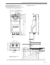
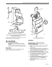
Fig. 5. ML6194/ML6294 Actuator standard
mechanical connection.
WIRING
WARNING
Electrical Shock Hazard.
Can cause severe injury, death or property
damage.
Disconnect power supply before installation. Actuators
with auxiliary switches can have more than one
disconnect.
All wiring must comply with local electrical codes, ordinances
and regulations. The ML6194/ML6294 are designed for use
with a Class 2 power supply. Voltage and frequency of
transformer used must correspond with characteristics of
motor and those of power supply. See Fig. 5 for standard
mechanical connection. See Fig. 6 through 9 for typical wiring
diagrams.
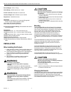
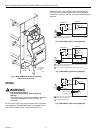
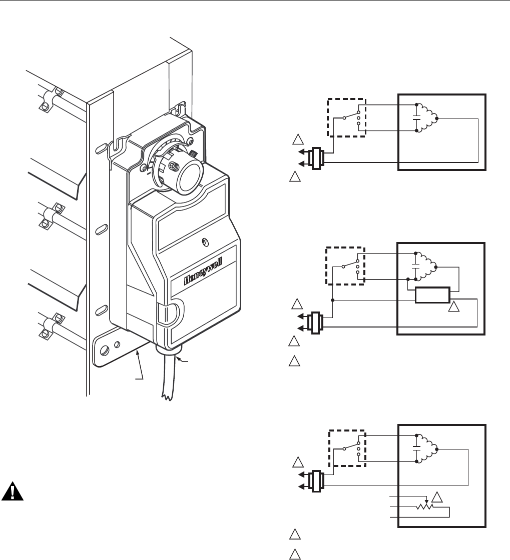
Fig. 6. ML6194A,C typical wiring diagram.
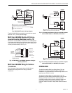
Fig. 7. ML6194D,F typical wiring diagram.
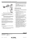
Fig. 8. ML6294A,C typical wiring diagram.
M11273A
MOUNTING
BRACKET
TO JUNCTION
BOX (UP TO
3 FT AWAY)
3
0
3
0
0
6
0
6
0
9
0
L1
(HOT)
L2
1
1
MOTOR
24 VAC
B
BLUE
W
YELLOW
T2
BLACK
ML6194A,C
M11283
A
POWER SUPPLY. PROVIDE DISCONNECT MEANS AND OVERLOAD
PROTECTION AS REQUIRED.
CONTROLLER
L1
(HOT)
L2
1
1
2
2
MOTOR
TIME OUT
24 VAC
B
BLUE
W
YELLOW
T2
RED
T1
BLACK
ML6194D,F
M11282
A
POWER SUPPLY. PROVIDE DISCONNECT MEANS AND OVERLOAD
PROTECTION AS REQUIRED.
TIME-OUT FUNCTION AVAILABLE WITH ML6194D,F MODELS.
CONTROLLER
L1
(HOT)
L2
1
1
2
2
MOTOR
24 VAC
B
BLUE
W
YELLOW
T1
BLACK
ML6294A,C
M11281A
POWER SUPPLY. PROVIDE DISCONNECT MEANS AND OVERLOAD
PROTECTION AS REQUIRED.
500 OHM POTENTIOMETER.
ORANGE (OPEN)
TAN
GREEN (CLOSED)
CONTROLLER