


63-2498—2 B.B. Rev. 6-00 www.honeywell.com
Home and Building Control Home and Building Control
Honeywell Inc. Honeywell Limited-Honeywell Limitée
Honeywell Plaza 155 Gordon Baker Road
P.O. Box 524 North York, Ontario
Minneapolis, MN 55408-0524 M2H 3N7
Printed in U.S.A. on recycled
paper containing at least 10%
post-consumer paper fibers.
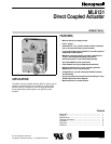
ML6131 DIRECT COUPLED ACTUATOR
OPERATION
VAV Systems
VAV systems control the temperature within a space by
varying the volume of supply air. Air is delivered to the space
at a fixed temperature. The volume of supply air is controlled
by the space thermostat modulating the supply air damper.
When full heating and cooling flexibility is required in a zone, it
is handled by temperature air system, or with reheat capability
in the air terminal units. As individual zones shut down, the
total air flow in the system is regulated by a central duct static
pressure controller. The fan system is sized to handle an
average peak load, not the sum of the individual peaks. As
each zone peaks at a different time of day, extra air is
borrowed from the off-peak zones. This transfer of air from
low-load to high-load zones occurs only in true VAV systems.
In pressure independent systems, individual zone airflow
sensors are used to maintain the zone air flow rate regardless
of fluctuation in the total system pressure.
Pressure independent systems, when used with controllers
such as the W7620, can react faster to changes in air flow
demand. Therefore, these systems can use the faster
15 second ML6131 models.
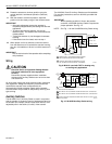
Parallel Actuators
IMPORTANT
Over time, parallel-driving actuators can become out
of sync with each other. Normally, driving all
actuators to the fully-open or fully-closed position
puts them back in sync.
Using Fig. 9, parallel the CW, COM and CCW terminals. Make
certain the total connected load does not exceed the current
capacity of the controller or thermostat.
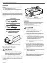
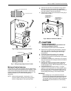
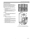
CHECKOUT
To check out the ML6131, determine the direction the damper
shaft moves to open the damper (cw or ccw). See Fig. 3:
1.
Place 24 Vac across the appropriate COM and CW or
COM and CCW terminals to energize the actuator. The
ML6131 should begin to open the damper.
2.
If the actuator does not run, switch the 24 Vac across
the opposite COM and CW or COM and CCW terminals
to determine if the damper will begin to close.
3.
If the actuator does not run in either direction, replace
the ML6131.
In the event the ML6131 is used with a spdt floating wall
thermostat (pressure dependent systems):
1.
Adjust the setpoint of the thermostat to call for cooling.
2.
Observe the operation of the actuator; if the device is
closed, it should begin to open.
3.
If not, adjust the setpoint of the thermostat higher to
determine if the wiring is correct.
4.
If no movement is observed, check for the presence of
24 volts.
5.
If using the T641 Thermostat, check that 24 volts are
present between terminals C and Y during a call for
cooling. With proper wiring and 24 volts present, the
actuator should operate correctly.
6.
If not, replace the actuator.
NOTE: When the ML6131 is used with electronic
control systems such as the W7620, override
the control system by programming the
controller to open/close the zone damper as
appropriate.