


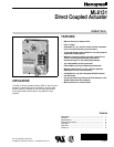
ML6131 DIRECT COUPLED ACTUATOR
63-2498—26
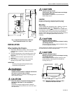
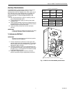
10.
Rotate the actuator to minimum position using the
manual declutch; see Manual Operation (Declutch)
section.
11.
With the actuator at minimum position, adjust the
position more accurately using air flow measurements.
IMPORTANT
— After each adjustment, ensure the actuator is
completely stopped before proceeding with the next
adjustment.
— To reduce the minimum position, turn out the
setscrew (ccw). The actuator then drives toward the
closed position.
— Turning the setscrew in (cw) damages the actuator
housing.
— If the device is too far closed, return to step 1.
12.
When proper air flow is achieved, loosen the locknut
from the setscrew until it contacts the actuator housing,
then turn it an additional 1/8 turn to lock the setscrew in
place.
IMPORTANT
Run an entire check of the operation after completing
this procedure.
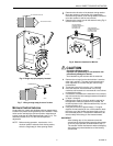
Wiring
CAUTION
Electrical Shock or Equipment Damage Hazard.
Can shock individuals or short equipment
circuitry.
Disconnect all power supplies before installation.
Actuators with auxiliary switches can have more than
one disconnect.
All wiring must comply with local electrical codes, ordinances
and regulations. Voltage and frequency of the transformer
used with the actuator must correspond with the
characteristics of both the power supply and the actuator.
Screw terminals are provided for easy hookup. See Fig. 9 for
typical wiring.
Auxiliary Switches
The 201052A, B or C Auxiliary Switch is used in conjunction
with the actuator. It allows for control of equipment external to
the actuator (for example, electric reheat coils and fan) at an
adjustable point in the stroke (0° to 90°) of the actuator.
The 201052A, B and C Auxiliary Switches are field-addable.
For mounting instructions, see form 63-2218, provided with
the device.
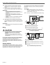
IMPORTANT
When operating an ML6131 from a two-position
controller, a 201052B Auxiliary Switch is required for
proper operation. See Fig. 10.
NOTE: See Fig. 11 for the 201052B Auxiliary Switch wiring.
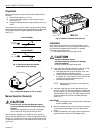
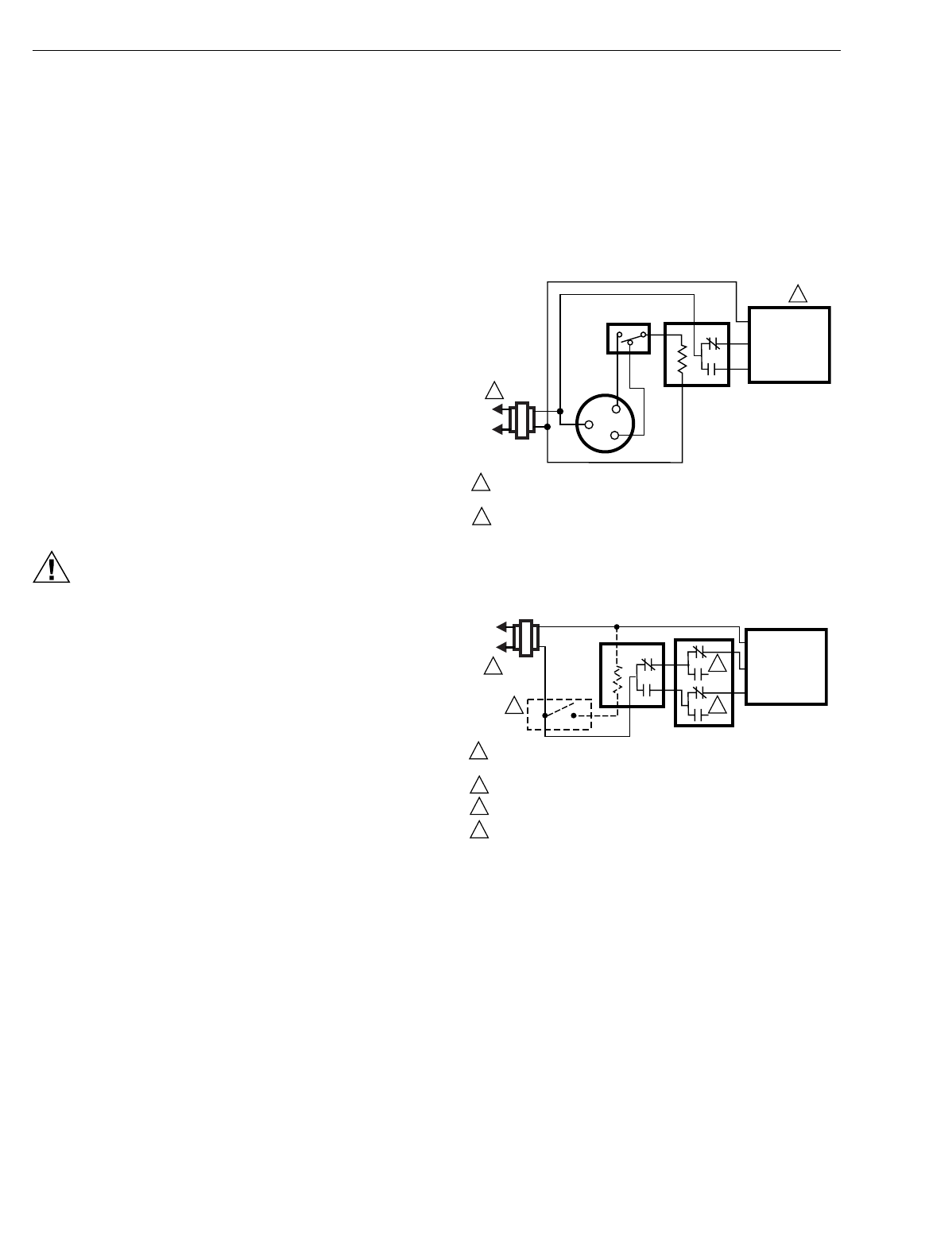
Fig. 9. ML6131 used with T87F in heating-only
or cooling-only application.
Fig. 10. 201052B Auxiliary Switch wiring.
M17613
EXTERNAL
SWITCH
R
W
Y
T87F
R8222
RED COM
BLUE CW
WHITE CCW
L1
(HOT)
L2
1
1
2
2
POWER SUPPLY. PROVIDE DISCONNECT MEANS
AND OVERLOAD PROTECTION AS REQUIRED.
AUXILIARY SWITCHES ARE REQUIRED TO TURN
OFF THE MOTOR AT EACH END OF THE STROKE.
ML6131
M17612
SPDT
CONTROL
ON/OFF
CONTROL
RED COM
BLUE CW
WHITE CCW
L1
(HOT)
L2
1
1
4
2
3
2
3
4
POWER SUPPLY. PROVIDE DISCONNECT MEANS AND OVERLOAD
PROTECTION AS REQUIRED.
SET SWITCH TO CLOSE WHEN STROKE REACHES FULL CW POSITION.
SET SWITCH TO CLOSE WHEN STROKE REACHES FULL CCW POSITION.
ON-OFF CONTROL REQUIRES AN R8222 SPDT RELAY IN PLACE OF THE
SPDT CONTROL.
ML6131
201052B