


ML6131 DIRECT COUPLED ACTUATOR
63-2498—24
Preparation
Before mounting the actuator onto the shaft, determine the
following:
1.
Size of the shaft (3/8 in. to 1/2 in.).
2.
Direction the shaft rotates to open the device (cw or
ccw). See Fig. 3.
3.
Degrees of actuator stroke for opening device (45°, 60°,
or 90°).
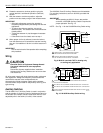
If the shaft is 3/8 in. round or square, use part number 201391
Shaft Adapter provided inside the bag assembly shipped with
the actuator. Place the adapter opposite the setscrews
(see Fig. 4).
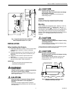
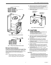
Fig. 3. Determining direction damper
shaft rotates when opening.
Fig. 4. Using shaft adapter for 3/8 in. shafts.
Manual Operation (Declutch)
CAUTION
Personal Injury and Product Damage Hazard.
Do not use manual declutch without supporting
the load.
Support load independent of actuator immediately
prior to and while using manual declutch lever.
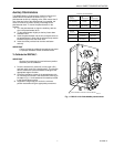
Manual declutch capability is available on some actuators.
Use the manual declutch lever to manually adjust the actuator
setting. Fig. 5 shows the location of the manual declutch lever.
To operate, push the lever in the direction of the arrow on the
lever cover.
Fig. 5. Location of manual declutch lever.
Installation
After determining the direction of the shaft rotation (cw or
ccw), install the device. For valve linkage mounting, refer to
the instructions shipped with the linkage. For damper
mounting, proceed as follows:
1.
Place the actuator onto the damper shaft.
CAUTION
Equipment Damage Hazard.
Improper range stop selection can damage
light-duty dampers.
Be sure to select the proper range stop.
2.
If the angle of the damper opening is either 45° or 60°,
close the actuator using the manual declutch:
a. Disengage the hub using the declutch lever; see
Manual Operation (Declutch) section.
b. Rotate the hub until the actuator gear train passes
the proper 45° or 60° setting. (Do not insert the pin
until after the actuator passes this point.)
c. Release the declutch lever.
NOTE: Dampers with 90° stroke do not require the
range stop pin.
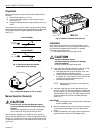
3.
Insert the range stop pin into the appropriate (cw or
ccw) 45° or 60° slot. The range stop pin is clipped into
its final position only after the pin passes through both
actuator plates (see Fig. 6). The range stop pin should
snap into position and not be removable manually
(see Fig. 7).
IMPORTANT
Do not fully tighten the mounting screw; the actuator
must be allowed to float.
4.
With the actuator placed in its final position, secure the
mounting tab to the damper box with a sheet metal
screw.
5.
Position the damper in the open position and securely
tighten the Allen screws into the damper shaft.
COOLING
AIR FLOW
COOLING
AIR FLOW
CW TO OPEN, CCW TO CLOSE
CCW TO OPEN, CW TO CLOSE
M2067A
TYPE A DAMPER
TYPE B DAMPER
SHAFT ADAPTER
M2064
ML6131
M17611
DIRECT COUPLED ACTUATOR
ML6131
MANUAL
DECLUTCH
LEVER