


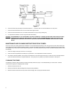
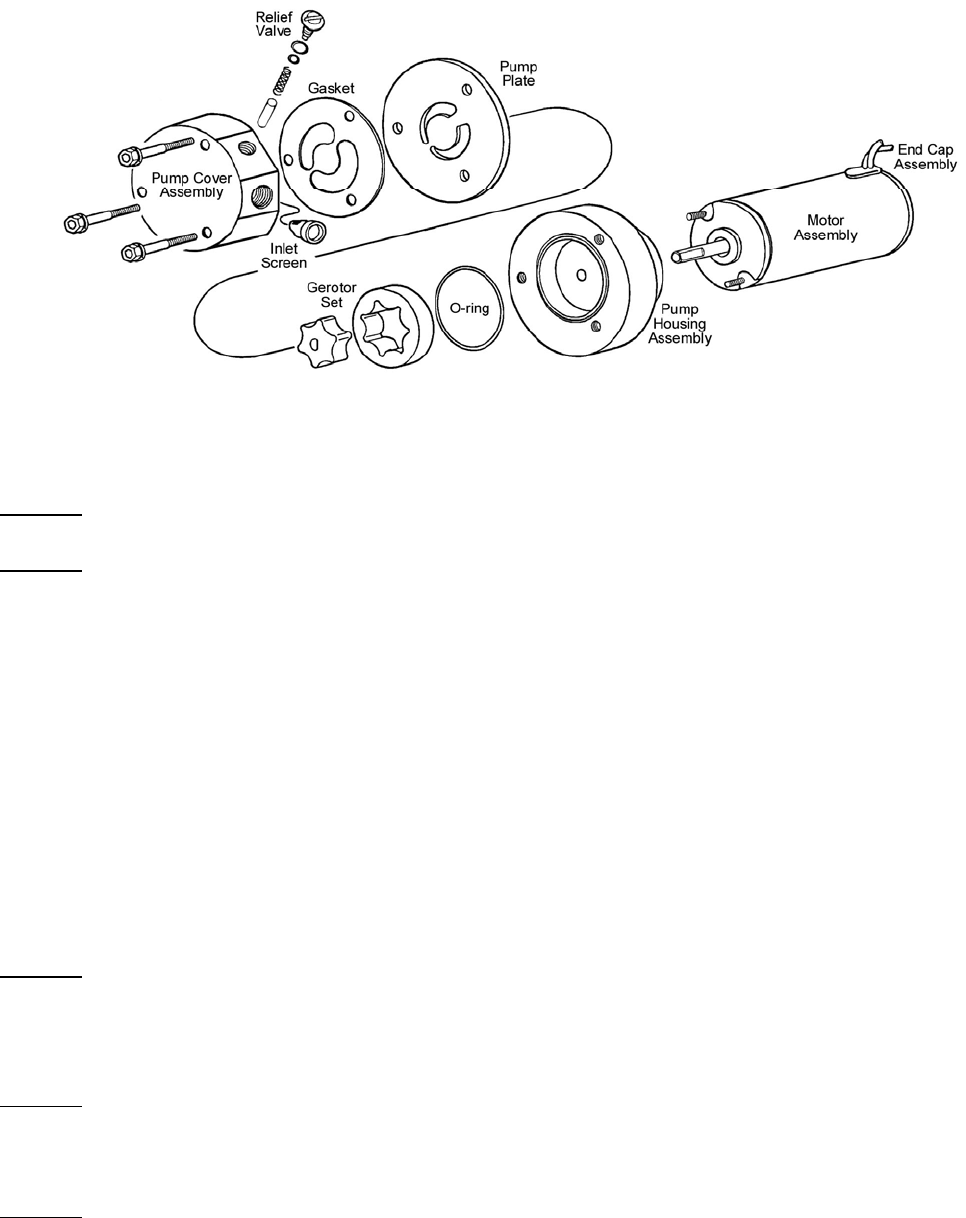
Figure 4
4. Turn the pump upside down, remove the three bolts, and carefully lift off the pump cover followed by the gasket, pump plate, and O-Ring.
5. Very carefully remove the gerotor assembly (both parts) from the pump housing.
WARNING!
KEEP THE GEROTOR TOGETHER AS A MATCHED SET. THIS ASSEMBLY MUST BE REASSEMBLED THE SAME WAY IT
WAS DISASSEMBLED. THE TOP OF EACH PART MUST REMAIN TOWARD THE TOP OF THE PUMP.
WARNING!
DO NOT IMMERSE THE ENTIRE UNIT IN ANY LIQUID. IMMERSION COULD DAMAGE THE ELECTRICAL CIRCUITRY,
RESULTING IN A PUMP MALFUNCTION. A PUMP MALFUNCTION COULD RESULT IN A FIRE, WHICH MAY RESULT IN
PROPERTY DAMAGE, SERIOUS INJURY, OR DEATH.
6. Remove the relief valve plug along with the O-Ring and shim. Not all pumps use a shim. Then remove the spring and relief valve piston.
7. Do not remove the motor assembly from the pump housing assembly. If the pump seal is leaking, please call Holley Tech Service at 270-
781-9741 for assistance.
8. Clean the housing assembly, pump plate, and pump cover assembly with any good quality spray-type carburetor cleaner. Make sure the
gasket surfaces are clean. Blow parts dry with compressed air. Clean any loose Teflon sealant, etc. from the inlet and outlet ports.
9. Inspect the gerotor assembly and its corresponding contact surfaces for damage such as pits, gouges, or deep scratches. Damage and
wear of this nature can greatly affect the pump’s performance. Suspect components should be replaced.
10. Reassemble the pump in reverse order of the disassembly. Lubricate all friction surfaces during the assembly with WD-40 or equivalent.
11. Insert the relief valve piston into the pump cover assembly. The rubber end goes in first, followed by the spring. Replace the relief valve
plug with the O-Ring, making sure to replace the small brass shim on the end, if used on your pump.
12. Turn the pump housing over and insert the gerotor assembly. Keep the same sides up.
WARNING!
MAKE SURE THE GEROTOR ASSEMBLY IS REPLACED IN THE SAME ORIENTATION AS WHEN IT WAS DISASSEMBLED.
KEEP THE SAME SIDES UP.
13. Set the large O-Ring in place on the pump housing along with the pump plate, gasket, and pump cover assembly. These parts can only be
positioned one way in order for the bolt holes to align. Apply a drop of Loctite to each screw. Insert the bolts and tighten to 50-60 in./lbs. of
torque.
WARNING!
OVERTIGHTENING CAN CAUSE THE PUMP BASE TO CRACK ALLOWING FUEL TO LEAK. A FUEL LEAK CAN CAUSE A
FIRE AND/OR EXPLOSION, RESULTING IN PROPERTY DAMAGE, SERIOUS INJURY, AND/OR DEATH.
14. Replace the inlet filter screens along with the fuel fittings. Teflon paste can be used on the fittings and they should be torqued to 15 ft./lbs.
See the warning above.
WARNING!
DO NOT USE TEFLON TAPE ON PUMP FITTINGS. THIS TAPE CAN BREAK DOWN WHEN IT COMES IN CONTACT WITH
FUEL. THE TEFLON TAPE MAY PLUG THE FUEL PUMP, CAUSING DAMAGE TO THE PUMP AND THE FUEL SYSTEM.
15. Reinstall the pump in the vehicle.
5