


XL-FW232-02 7
REBUILDING PROCEDURES continued
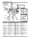
Swinging Lock Installation
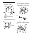
1. Place the swinging lock (6) into position, compressing
spring (
7). For spring position, see FIGURE 3.
NOTE: The lock pin (5) has a hole for a grease
fitting (
25).
Position the pin
so that the hole
faces the front
of the casting.
Drive the lock
pin (
5) through
the holes in the
casting and
swinging lock
and secure with
a cotter pin (
4).
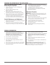
Install the
grease fitting so
that it faces to
the side and
will be accessible
from the left side of the tractor. (See
FIGURE 14).
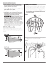
2. Turn the fifth wheel upright.
Check the Primary Lock Operation:
1. Lock the fifth wheel using a Holland TF-TLN-5001 (2˝)
lock tester (
35) or a Holland TF-TLN-1500 (3
1
⁄2˝)
lock tester (
35A) (as appropriate for the fifth wheel
being rebuilt).
Refer to HOLLAND Publication XL-FW340
for description and instructions for Holland TF-TLN-5001
Lock Adjustment Tool and, Publication XL-FW130 for
Holland TF-TLN-1500 Kingpin Lock Tester.
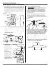
2. Pull the primary release handle (16) out, raise it up
and engage the handle lug with the top plate casting
(see
FIGURE 15).
3. Pull the primary release handle (
16) out further and
install a small piece of 1/4˝ stock (not supplied)
between the handle lug and the casting.
4. Unlock the fifth wheel by removing the lock tester.
When operating properly, this action will drop the
1/4˝ stock and the release handle will drop down
and move to the locked position.
5. If the 1/4˝ stock does not drop out, go back to
STEP 5
on page 6 and bend the release lever (15) slightly in
the opposite direction.
6. Repeat
STEP 4, above.
7. Turn the fifth wheel back over.
IMPORTANT: Before proceeding with Secondary Lock
Installation, turn to page 10 to determine which instruc-
tions you should follow.
Secondary Lock Installation:
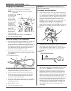
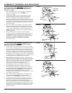
1. Position the secondary lock (10) in the closed position
in the casting, as shown in
FIGURE 16. Complete Steps
1
, 2, and 3 before installing the spring, release handle,
and the secondary lock pin. Align the secondary lock
pin holes. Rotate the secondary lock until it makes
contact with the casting at point
C as shown in
FIGURE 16. Check the rough location of the end of the
secondary lock in relation to the swinging lock.
It should be 3/16˝ (0.188˝) ± 1/16˝ (0.06˝) from
point
A on the swinging lock (see FIGURE 16) when the
secondary lock is resting against the casting at point
C.
2. If the dimension is less than 1/8˝ (0.125˝), remove the
secondary lock (10) and place a bead of weld on the
fifth wheel casting at point
C and grind smooth.
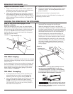
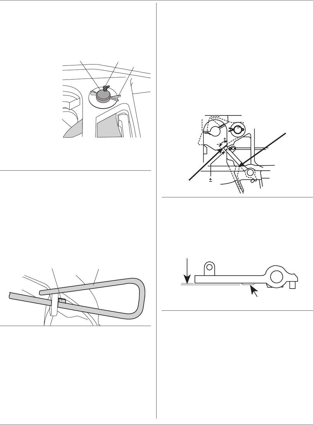
If the dimension is greater than 1/4˝ (0.25˝), remove
the secondary lock and grind at point
D as shown
in
FIGURE 17.
3. After a final check of the dimensions, coat the lock pin
hole in the secondary lock (
10) with Never-Seez
®
(sup-
plied with kit).
DO NOT use a substitute lubricant.
4. Install the secondary lock release handle (
9) into
the casting. Install the secondary lock (
10) onto the
handle. Install the cotter pin (
8) in the handle and
spread it. Drive the secondary lock pin (
3) through the
holes in the casting and the secondary lock, and
secure with a cotter pin (
2). Install a grease fitting (25)
in the lock pin so that the fitting faces the side, and
will be accessible from the left side of the tractor.
Install spring (
11) by fitting the small diameter end
over the projection on the secondary lock (
10) and
the large diameter end into the spring pocket in
the casting.
6
5 25
4
FIGURE 14
16
Release handle lug
FIGURE 15
3/16˝ 1/16˝
A
C
FIGURE 16
D
Grind flush if necessary but
do not exceed flush condition.
FIGURE 17