


Page 7SKU 98135 For technical questions, please call 1-800-444-3353.
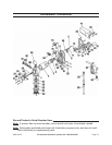
Strip 6” of the outer insulation cover-3.
ing the Cable (60) being careful not to
damage the wire insulation.
Pass the stripped end of the Cable 4.
(60) through the Cable Connector
(53) until 2” of the unstripped wire is
within the Motor Casing Assembly
(6).
Strip 1/2” of the insulation from the 5.
ends of the Cable (60). Connect
these wires to the matching colored
Pump Wires using wire nuts (not sup-
plied).
Fold all wires into the Motor Casing 6.
assembly (6) and replace the Junc-
tion Box Cover (18). Make sure all
screws are seated so there is no
space between the Junction Box
Cover (18) and the Motor Casing As-
sembly (6).
Run the Cable (60) to the 12 Volt 7.
DC battery or similar power source.
Support the Cable (60) as necessary
and protect it from heat, sharp edges
or any other obstacle that could dam-
age it.
Strip the outer Cable (60) covering 8.
as necessary. Make a secure con-
nection to the tank, barrel, drum or
vehicle with the Ground Wire (51).
NOTE: To determine if a vehicle 9.
system is negative (-) or positive
(+), check the battery marking of
the terminal that is wired to the
vehicles frame or motor block. For
vehicles with negative (-) ground,
connect the negative (black) wire
to the vehicle frame. For vehicles
with positive (+) ground, connect
the positive (red) wire to the ve-
hicle frame.
If attaching to a vehicle, attach one 10.
end of a 30 amp fuse holder to the
end of the remaining wire. Connect
the other end of the fuse holder to
the ungrounded side of the power
source. The battery terminal or the
end of the battery cable is recom-
mended.
Check all connections to make sure 11.
they are correct. Install the 30 amp
fuse in the fuse holder.