


120 v
280v
240v
Com.
White
Violet
Orange
Black
Transformer
T2
T2
R
W
B
T2
T1
Control Device
L1 (Hot)
L2
Transformer
Ye
llow
Red
Blue
Com.
N.C.
N.C.
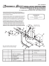
8. Wire the actuator according to the
appropriate wiring illustration that
identifies the actuator’s electrical
connections. Wiring should be per an
approved project or job wiring diagram
and must comply with all applicable
electrical codes
Note: Tape or wire nut all unused leads.
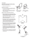
9. Apply power to the actuator.
The damper blades should fully open or
close and return to the fail position when
power is disconnected, if they do not,
adjustments can be made by resetting
the crankarm position on the damper or
actuator shaft, or by adjusting the 3 in.
dimension on the damper shaft crankarms.
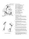
Auxiliary Switch Wiring Connections
(All colors are tracers on white wire)
Model M9185 Wiring Connections
Note: This is a modulating actuator that
requires a control signal to operate.
Model M4182 Wiring Connections
Note: Model M8182 is a 24 Volt actuator
with no transformer. Connections must
be made directly to T1 and T2.
Copyright © 2005 Greenheck Fan Corporation
454200 Honeywell M4182, M8182, M9185 IOM
Rev. 5 August 2005
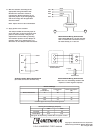
Electrical Ratings
Voltage
(V@ 50/60 Hz)
Current Draw
(A)
Power consumption
(W)
Without Transformer
24
.86
20
With Internal Transformer
120
.25
25
208
.14
25
240
.13
25
Controller Type: Two wire, on-off switching action
Auxiliary Switch Ratings (Amperes)
120V
240V
Full Load
7.2
3.6
Locked Rotor
43.2
21.6
Ratings for 40 VA pilot duty, 120/240 VAC on opposite contact