


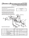

6. Assemble the linkage
Parts needed for dampers with
1
/
2
in. shafts:
(Qty.
2
)
1
/
2
in. crankarms (item 7)
(Qty.
2
)
5
/
16
- 18 x 1
1
/
2
in. bolts ( item 8)
(Qty.
2
)
5
/
16
- 18 spinlock nuts ( item 9)
(Qty.
1) Drive link (item 15)
(Qty.
2
) Linkage adjustment pin (item 13)
(Qty.
2
)
1
/
4
/4/
- 20 spinlock nuts (item 6)
(Qty.
1) Actuator crankarm (item 19)
(Qty.
2
)
1
/
4
/4/
in. E-Ring (item 14)
Parts needed for dampers with 1 in. shafts:
(Qty.
1) 1 in. crankarm (item 10)
(Qty.
1)
3
/
3
/
3
8
-16 x
2
1
/
2
in. bolts (#11)
(Qty.
1)
3
/
3
/
3
8
-16 spinlock nut (#12)
(Qty.
1) Drive link (#15)
(Qty.
2
) Linkage adjustment pin (#13)
(Qty.
2
)
1
/
4
/4/
in.
- 20 spinlock nuts (#6)
(Qty.
1) Actuator crankarm (#19)
(Qty.
2
)
1
/
4
/4/
in. E-Ring (#14)
-
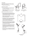
6a. Assemble the shaft crankarms.
For dampers with
1
/
2
/2/
in.
shafts:
The damper shaft crankarms must be placed as mirror
images of each other, meaning the like sides face each
other. The bolts and nuts are to be positioned as in the
exploded view.
For dampers with 1 in. shafts:
The 1 in. crankarm, item 10, must be in the position
shown in the encircled exploded view shown above left.
Position the bolt and nut as shown in the same diagram.
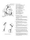
6b. For dampers with
1
/
2
/2/
in.
shafts:
Insert a linkage adjustment pin through both of the
crankarm slots. Position it 3 in. from the center of the
damper shaft. Secure it there with a
1
/
4
/4/
-20 spinlock nut
(item 6).
For dampers with 1 in. shafts:
Insert a linkage adjustment pin through the 1 in. crankarm
(item 10) slot. Position it 3 in. from the center of the
damper shaft. Secure it there with a
1
/
4
/4/
-20 spinlock nut
(item 6).
6c. Attach the drive link to the damper shaft crankarms by
inserting the linkage adjustment pin through one of the
drive link’s holes and fastening it with an E-ring (item 14).
6d. Attach the drive link to the actuator crankarm with the
linkage adjustment pin, a spinlock nut and an E- ring
(item 14). Set the linkage adjustment pin 2
1
/
8
in. from the
actuator shaft center and secure it there with the spinlock
nut. Fasten the other end through the empty drive link hole
with the E-ring (item 14).
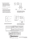
7. Note the damper shaft rotation for fail direction and orient
the linkage appropriately as shown in the linkage
illustration. The damper linkage is now in its fail position
Position the damper blades to their proper position (open
or closed). Tighten the bolts
14
15
19
6
13
14
13
7
8
9
11
10
12
Steps 6a
,
b for dampers
with 1 in. shafts
(substitute these parts in
place of 7, 8, 9, &13)
Steps 6a
,
b
for dampers with
1
/
2
in. shafts.
3"
Power Position
Fail Position
Return Power
2
1
/
8
"
Damper
Shaf
t
Counter-Clockwise to
Fail Position
Clockwise to Fail Position
Fail Position
Return Power
3"
2
1
/8"
Power Position