


Instructions:
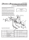
These installation instructions assume the damper is already
mounted in a duct or sleeve with the damper shaft extending
beyond the sleeve or duct 6 inches.
1. Install the stand off bracket (item 16).
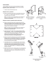
Dampers with a jackshaft
1a. Mount the stand off bracket onto the jackshaft bracket with
(4)
1
/
4
/4/
-20 X
1
/
2
in. thread cutting screws (item 17). Use the
orientation shown on this page.
Note:
The bracket must be perpendicular to the damper on
the duct or sleeve and the bracket's shaft hole must be
centered on the jackshaft.
Dampers without a jackshaft (Shaft Extension)
1b. Mount the stand off bracket (item 16) spanning across the
damper frame flanges. Use the orientation shown to the right.
Fasten to the damper frame with (4) #14 Tek screws, supplied
in the field. Be sure not to run the screws into the damper
linkage, which is between the flanges.
Note:
The bracket must be perpendicular to the damper on
the duct or sleeve and the bracket's shaft hole must be
centered on the shaft extension.
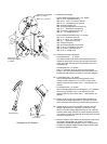
2. Fasten the mounting plate (item 3) to the mounting bracket
(item 2) using (4)
1
/
4
/4/
- 20 x
1
/
2
in. thread studs (item 4), and (4
)
1
/
4
/4/
-20 spinlock nuts (item 6), through the matching four hole
pattern on the mounting bracket labeled “A” on the
illustration. Note that the mounting bracket has only one
pattern that will match the mounting plate pattern.
3. Mount the mounting bracket (item 2) to the stand off bracket
using (4
)
1
/
4
/4/
-20 x
1
/
2
in. bolts (item 21) and (4
)
1
/
4
/4/
-
20 Spinlock
nuts (item 6) included with this kit. Use the outer four holes of
the mounting bracket for jackshafted models and the inner
four holes for directly driven models.
4. If the damper has a
1
/
2
in. dia. damper shaft, mount the ball
bearing (item 18), into the mounting bracket with two #10 Tek
screws (item 20). The Tek screws are required to keep the
thrust forces from pushing the bearing out of the mounting
bracket. If the damper shaft is 1 in. in diameter then no ball
bearing is required.
5. Mount the actuator to the mounting plate in the corresponding
holes using
(
3
)
1
/
4
/4/
-
20 x
3
/
3
/
3
4
/4/
in. thread cutting screws (item 5).
Note that the actuator must be mounted with the shaft in the
horizontal position.
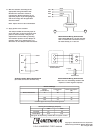
A
A
Mounting Plate
Damper
3"
Power Position
Fail Position
Return Power
2
1
/
8
"
Damper
Shaf
t
Counter-Clockwise to
Fail Position
Clockwise to Fail Position
Fail Position
Return Power
3"
2
1
/8"
Power Position
Orientation of Stand Off
Bracket for a directly driven
damper
Orientation of Stand Off
Bracket for a jackshaft
driven damper