


ENGINE APPLICATION MANUAL GM Powertrain
Gasoline 4.3L V6 90 Degree Revised: 08/15/2000
File: c:\data\manuales\v6-truck\am43v6#3.doc
Contact:Luis Nespolo - (248) 857-1558 Printed: 8/15/00
29
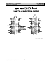
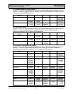
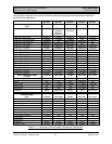
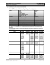
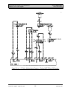
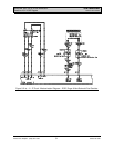
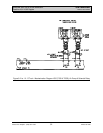
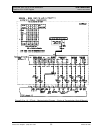
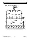
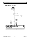
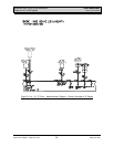
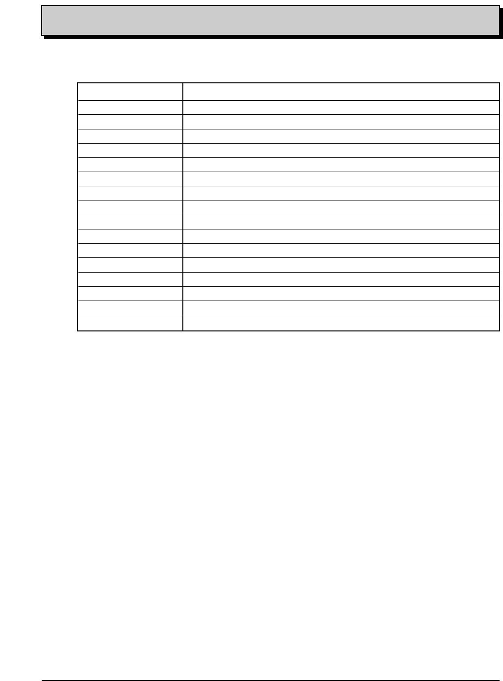
Figure 3.2.1-I to 3.2.1-XVI shows the PCM Engine to Vehicle Mechanization Diagram for the P-
Truck platform application.
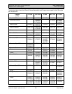
Figure Number Description
Figure 3.2.1 - I Cooling, MAP, TPS and OIL Sensors
Figure 3.2.1a – II EGR, Purge & Vent Solenoid Fuel Canister
Figure 3.2.1a - III VSS (TISS & TOSS), Air Pump & Solenoid Relay
Figure 3.2.1a - IV Engine to Transmission (Auto & Manual)
Figure 3.2.1a - V Engine Injectors
Figure 3.2.1a - VI TCC Switch & Cruise Control
Figure 3.2.1a - VII Starter, Alternator & IP Gages
Figure 3.2.1a - VIII Brake, ABS Switch, Serial Data Link I/P Cluster & Cruise Module
Figure 3.2.1a - IX Oxygen Sensors
Figure 3.2.1a - X Idle Air Controller & Knock Sensor
Figure 3.2.1a - XI Fuel System and Optional ETC
Figure 3.2.1a - XII Engine Ignition System
Figure 3.2.1a - XIII Engine Crank & Cam Sensors
Figure 3.2.1a - XIV HVAC
Figure 3.2.1a - XV Power Distribution
Figure 3.2.1a - XVI Note & references