


GPSMAP 400/500 Series Installation Instructions 9
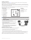
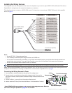
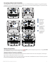
Connecting Cables to the Chartplotter
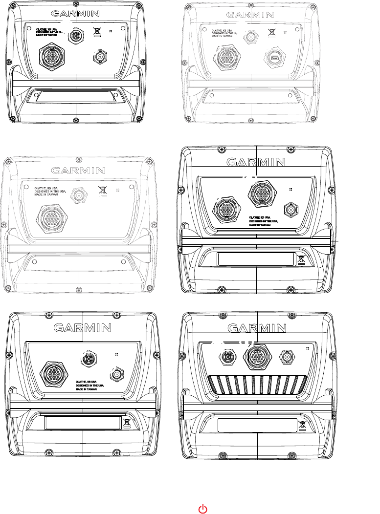
Use the diagrams below to help identify the connectors on the back of your GPSMAP 400/500 series chartplotter. Every possible chartplotter
conguration is not represented in the diagrams, but every possible connector type is listed for identication purposes. Every connector on the
back of the chartplotter may not be used for all installations.
➊
Wiring harness
➋
NMEA 2000
➌
External GPS
antenna (sold
separately)
➍
Compatible XM
antenna with
audio adapter
(sold separately)
➎
Compatible XM
antenna (sold
separately)
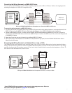
GPSMAP 526, 536, 546, and 556
GPSMAP 420, 430, 431, 440, and 450
GPSMAP 430x and 440xGPSMAP 421, 441, and 451
➊
➋
➌
➌
GPSMAP 521, 541, 551
GPSMAP 530, 535, 540, and 545
➎
➌
➊
➍
➋
➌
➋
➊
➊
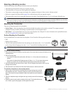
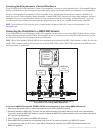
Testing the Installation
To turn on your chartplotter for the rst time, press and hold the key until the chartplotter beeps and turns on. Using the ROCKER
and the keys, follow the screens to congure your chartplotter.
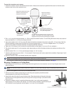
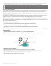
Testing the Optional Transducer Installation
Because water is necessary to carry the sonar signal from the sounder, the transducer must be in the water to work properly. You cannot get a
depth or distance reading when the transducer is out of the water.
When you place your boat in the water, check for leaks around any screw holes that were added below the water line. Do not leave your boat in
the water for an extended period of time without checking for leaks.