


GPSMAP 400/500 Series Installation Instructions 5
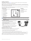
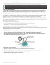
6.RoutethetransducercabletotheGPSMAP400/500serieschartplotterusingcabletiestosecurethecabletothemotorshaft.Youcanll
theforward-facingportion(exceptthecabletiepocket)ofthetransducermountwithsealanttoavoidaccumulatingdebris.
Leave some slack in the cable to avoid damage while using the trolling motor.
Avoid routing the cable close to electrical wires or other sources of electrical interference.
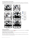
Shoot-Thru-Hull Installation
To avoid drilling a hole to mount a thru-hull transducer, a transom-mount transducer can be secured with epoxy inside a boat (shoot-thru-hull
installation). This type of installation can provide better noise reduction and allow you to use a higher gain setting. For a transducer to be
mounted inside the hull (shoot-thru, not thru-hull), the boat must be berglass with no core. Contact your boat manufacturer if you are unsure.
Professional installation might be necessary.
Some transducers are specically designed to be mounted inside a berglass hull. The standard plastic transom-mount transducer can also be
mounted using this method. If using a temperature-sensing transducer, the temperature displayed reects the hull temperature.
NOTE: A solid berglass hull can be no more than
5
/
8
in. (9.53 mm) thick when using a 500 W transducer, and no more than 1 in. (25.4 mm)
thick when using a 1 kW transducer. 1 kW transducers are only compatible with either the GPSMAP 525/535/545/555/526/536/546/556 or with
non “s” models compatible with a GSD 22.
When installing a transducer, consider the following:
The hull must be composed of solid berglass without air bubbles, laminates, llers, or dead air space.
The location must be in an area of clean (non-turbulent) water at all speeds.
The location must not be over any strakes or behind any obstruction on the hull that would create turbulence.
NOTE: Many modern hulls have a dedicated pocket for shoot-thru-hull transducer installation. If you are unsure whether your hull is equipped
with a pre-located pocket, contact your hull manufacturer.
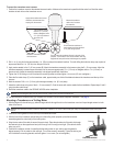
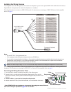
To test the location:
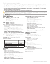
1. Fabricate a test device from a section of PVC pipe or a can, as shown in the following illustration.
2. TemporarilysealthetestdevicetothehullwithcaulkingorRTVsealer,andllthetestdevicewithwaterorlightmineraloil.
3. Place the transducer in the water, pointed directly at the bottom, weighted down. Set the device for optimum performance. If the sonar
performanceissignicantlydegraded,anotherlocationmustbetested.
Testing the Location
PVC pipe
or a can
Weight the transducer
to hold it in place.
Fill a pipe or a can with
water or a light mineral oil.
Hull surface
Strip caulk or
RTV sealer
To permanently install the transducer:
1. Lightly sand the surface of the hull and the face of the transducer with 400-grit wet or dry sandpaper.
2. Build a dam using strip caulk about
1
/
4
in. (6 mm) tall. Pour about
1
/
8
in.(3mm)oftwo-part,slow-cureepoxyintothedam.
3. Placethetransducerintheepoxy,turningthetransducertoworkoutanyairbubbles.
4. Weight the transducer in place, and allow it to cure for 24 hours.
•
•
•