


4 GPSMAP 400/500 Series Installation Instructions
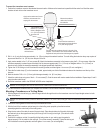
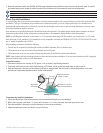
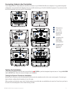
To mount the transducer on a transom:
1. Position the transducer mount at the selected transom location. Make sure the transducer is parallel with the water line. Mark the center
locations of each hole on the transducer mount.
Apply marine sealant to all screw
threads to prevent water from
seeping into the transom.
Mount the transducer
cable cover far above
the waterline.
The transducer should
extend
1
/
8
in. (3.2 mm)
below a berglass hull or
3
/
8
in. (9.5 mm) below an
aluminum hull.
Ensure that the transducer is
below water level when the boat
is on plane at high speed.
Do not mount the transducer directly in the path of the
propeller. The transducer can cause cavitation that may
degrade the boat performance and damage the propeller.
Mount the transducer parallel
with the bottom.
2. Drill
5
/
32
in.(4mm)pilotholesapproximately1in.(25mm)deepatthemarkedlocations.Toavoiddrillingtheholestoodeep,wrapapieceof
tape around the bit at 1 in. (25 mm) from the point of the bit.
3. Applymarinesealanttothe5×30mmscrews(B).Attachthetransducerassemblytothetransomusingthe5×30mmscrews.Adjustthe
transducerassemblytoextendbeyondthebottomofthetransomapproximately
1
/
8
in.(3.2mm)onberglasshullsor
3
/
8
in. (9.5 mm) on
aluminum hulls. Adjust the transducer assembly to be aligned parallel with the bottom.
4. Tighten the 10-32 locking nut until it touches the mounting bracket, and then tighten
1
/
4
turn more. (Do not overtighten.)
5.Placetherstcableclamp(F)onthetransducercable,approximatelyonethirdofthedistancebetweenthetransducerandthetopofthe
transom.
6. Mark the location. Drill a
1
/
8
in.(3.2mm)pilotholeapproximately
3
/
8
in. (9.5 mm) deep.
7.Attachthecableclampusingoneofthe4×12mmscrews(D).Coatthescrewwithmarinesealantbeforeinstallation.Repeatsteps5and6
using the other cable clamp.
8. Route the transducer cable to the GPSMAP 400/500 series chartplotter.
Avoid routing the cable close to electrical wires or other sources of electrical interference.
9. Test the transducer installation after you complete the GPSMAP 400/500 series chartplotter installation. See page 9.
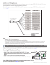
Mounting a Transducer on a Trolling Motor
1.Withtheridgesofthebandfacingup,slidethelargecabletiethroughtheslotonthetransducermountuntilequallengthsextendonboth
sides of the mount.
For cold water and heavy timber or debris areas, a metal 4-5 in. (100-125 mm) worm gear clamp is recommended instead of the plastic
cable tie.
2. Position the mount gasket on the curved top of the transducer mount.
3. With the front of the transducer pointed away from the trolling motor propeller, place the transducer
assembly against the motor body of the trolling motor.
4. Wrap the two ends of the cable tie around the motor body. Place the pointed end of the cable tie through
the fastener hole on the opposite end and pull it through until it is snug but not tight. (The cable tie clicks
when you pull it.)
5. Position the transducer so that it is parallel with the bottom when in use, making sure the gasket is
alignedproperly.Pullthecabletieenduntiltight.Trimofftheexcessifnecessary.Tightenthelockingnut
until it touches the mounting bracket, and then tighten
1
/
4
turn more. (Do not overtighten.)
Cable tie
Front of the transducer
Cable tie
Front of the transducer