


9
Installation
Wiring
the GPS 17
I
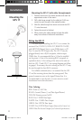
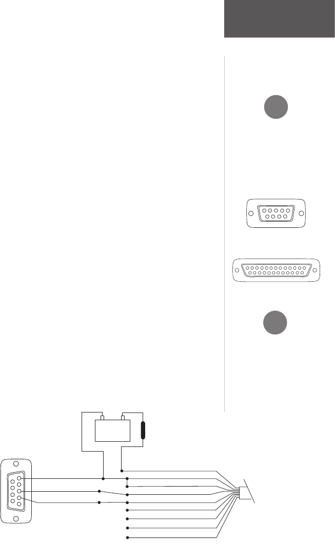
If the GPS 17 is being con-
nected to a PC, a DB9 or
DB25 serial connector (nor-
mally female) will be needed.
Check with a PC or electronics
supplier for this item.
Some non-Garmin devices
may have a separate data line
labeled “RETURN”, “DATA
GROUND” or “DATA -”. If
one of these lines exist, connect
the BLACK wire from the
power/data cable to it.
14
7
25
13
1
2
3
F
DB9 Female Serial Connector
DB25 Female Serial Connector
1
4
6789
2
3
5
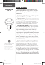
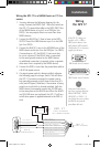
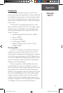
Wiring the GPS 17 to a NMEA Device or PC Con-
nector:
1. You may reference the following diagrams for the
wiring: Connect the WHITE (Port 1 Data Out) wire from
the GPS 17’s power/data cable to the DATA INPUT line
of the NMEA device or to pin 2 on a DB9 (pin 3 on
DB25). You may output data to no more than three
NMEA devices.
2. Connect the BLUE (Port 1 Data In) wire to the DATA
OUTPUT line of the NMEA device or pin 3 on the DB9
(pin 2 on DB25).
3. Connect the BLACK (-) wire to the GROUND wire of the
NMEA device and/or pin 5 on the DB9 (pin 7 on DB25).
If connecting to a PC, the BLACK (-) wire must also
be run to a ground. If the BLACK wire is connected
to the same ground terminal as the NMEA device,
no additional connection is required, unless a separate
data return line is required by the NMEA device).
4. Connect the RED (+) wire from the power/data cable to
a 8-40 Vdc power source.
5. If a remote power switch is being installed, reference
the following page for wiring a switch. This will allow
the GPS 17 to remain connected to a power source,
but manually powered on (pull down to less than 0.5
volts) and off (open). Otherwise, if the receiver is being
wired to a circuit which is already switched, (with the
NMEA device for example) connect the YELLOW wire
to the same place as the BLACK wire. When the BLACK
and YELLOW wires are combined, the GPS 17 will turn
on/off when power is applied/removed to the RED (+)
wire.
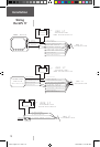
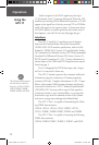
GPS 17
Power/Data Cable &
DB-9 Serial Connection
GPS 17
PIN 5: GROUN D
PIN
3: DATA OUT
PIN 2: DATA IN
1
4
6
7
8
9
Power/Data Cabl
e
Power Source
(-)
(+)
DB-9
Serial Connector
Fuse
1A
VIOLET: PORT 2 DATA OU T (n/c)
GREEN: POR T 2 DATA IN (n/c)
YELLOW : REMOTE ON /OFF
BLACK: GROUN
D
BLUE
: POR T 1 DATA IN
W H
ITE: POR T 1 DATA OUT
GRAY: PPS
(n/c)
RED: 6-40 VDC
BARE W IRE: DRAIN (n/c)
GPS 17 QSG rev C.indd 9 10/27/2004 11:06:55 AM