


8
Installation
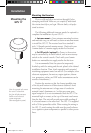
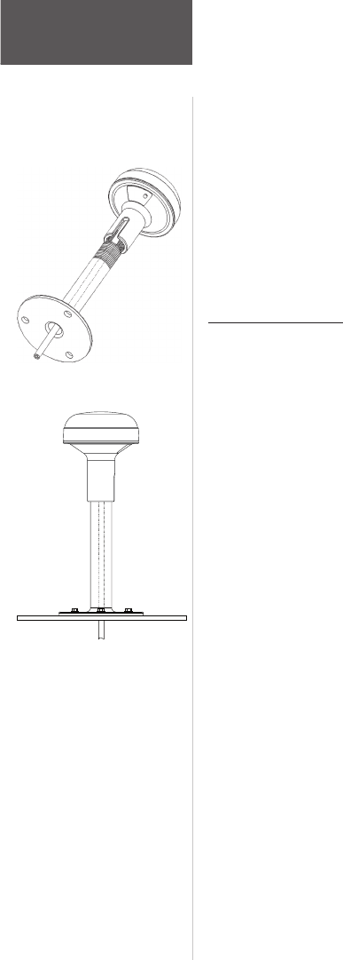
Mounting the
GPS 17
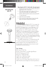
Wiring the GPS 17
The final step in installing the GPS 17 is to connect the
receiver’s Port 1 DATA IN, DATA OUT, REMOTE ON/OFF,
and GROUND (Return) lines to your NMEA device or PC.
Port 2 is used for RTCM input only. The GPS 17 may be
plugged directly into a RJ-45 receptacle, which accepts
NMEA data. It is recommended that a 1A fuse be installed
on the power (+) line of the receiving RJ-45 receptacle or
equivalent device. Color coding of the wires is the same on
both the GPS 17 and GPS 17 (see wiring diagrams on follow-
ing pages). If necessary, the wire coloring on the GPS 17 may
be seen through the clear RJ-45 connector.
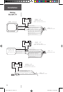
For reliable communication, it is essential that the GPS
17 and the receiving device share the same ground. This
ground connection acts as the (signal) Return line. It is
recommended to wire the unit to its own circuit to avoid
interference from other electronics.
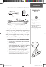
Mounting the GPS 17 with cable through mount:
1. Position the mount in the desire location and mark the
approximate center of the mount
2. Drill a hole large enough for the cable (or RJ-45 con
-
nector) to pass through at the marked location.
3. Slide the cable through the mount and screw the GPS
17 onto the mount.
4. Fasten the mount to the boat
5. When running the cable, attempt to keep the cable
away from sources of electronic interference.
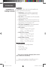
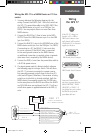
Wire Coloring:
RED- Power (+) 8-40 Vdc
BLACK- Ground (Power (-) and Data Signal Return)
YELLOW- Remote power On/Off
BLUE- Port 1 NMEA Data Input
WHITE- Port 1 NMEA Data Output
GREEN- Port 2 RTCM Data Input
VIOLET- Port 2 RTCM Data Output
(Reserved for Future Use)
GRAY- Pulse Per Second Output (See Technical Specifications)
GPS 17 QSG rev C.indd 8 10/27/2004 11:06:52 AM