


190-00228-20 GPS 16/17 Technical Specifications Rev. C
Page 25
APPENDIX B: BINARY PHASE OUTPUT FORMAT
Note: The following applies to GPS 17N software version 2.06 and higher, and all software versions of
GPS 16LVS, GPS 16HVS, GPS 16A, and GPS 17HVS.
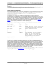
Two records are transmitted once per second by the GPS 16/17 series products. One record contains
primarily post-process information, such as position and velocity information. The second record contains
receiver measurement information. The records are sent at a default baud rate of 9600 baud, 8 data bits, and
no parity.
Records begin with a delimiter byte (10 hex). The second byte identifies the record type (33 hex for a
position record, 34 hex for a receiver measurement). The third byte indicates the size of the data. The fourth
byte is the first byte of data. The data is then followed by a checksum byte, a delimiter byte (10 hex), and
an end-of-transmission character (03 hex).
Note: If RTCM-104 differential data is sent to the GPS sensor the board will reset the Phase Output Data
baud rate to the same baud rate used for RTCM-104 data. If the differential inputs are used on the GPS
sensor then the RTCM-104 data must be sent to the GPS sensor at 9600 baud (preferred) or 4800 baud.
RTCM-104, baud rates less than 4800 baud are not supported by the GPS sensors since it would limit bus
bandwidth past the point where a once per second phase output data rate could be maintained.
Note that the satellite data information is also enabled when the position record is enabled.
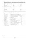
Records sent over RS232 begin with a delimiter byte (10 hex). The second byte identifies the record type
(33 hex for a position record, 34 hex for a receiver measurement and 72 hex for a satellite data record).
The third byte indicates the size of the data. The fourth byte is the first byte of data. The data is then
followed by a checksum byte, a delimiter byte (10 hex), and an end-of-transmission character (03 hex).
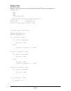
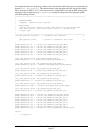
Additionally, any DLEs (0x10) that appear between the delimeters are escaped with a second DLE. There
is sample code at the end of this section that will strip off the DLEs and ETXs.
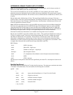
RS232 Packet:
- 0x10 (DLE is first byte)
- 0x## (Record ID – single byte)
- 0x## (Number of data bytes – single byte)
- data bytes (See descriptions below)
- 0x## (2’s complement of the arithmetic sum of the bytes between the delimiters)
- 0x10 (DLE)
- 0x03 (ETX is last byte)
The data bytes of each packet contain the record specified by the record ID. A description of each record
follows.
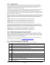
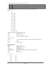
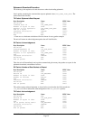
Satellite Data Record
The satellite data has a record ID of 0x72 with 84 (0x54) data bytes. The data bytes contain the data for the
12 channels as described below. For each satellite, the following data is available:
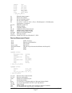
typedef struct
{
uint8 svid; //space vehicle identification (1–32 and 33–64 for WAAS)
uint16 snr; //signal-to-noise ratio
uint8 elev; //satellite elevation in degrees
uint16 azmth; //satellite azimuth in degrees
uint8 status; //status bit-field
} cpo_sat_data;