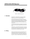
GPS16-HVS GPS Receiver
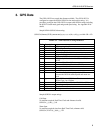
TABLE 2-2. Wiring without the RJ45 Connector
(Garmin Wiring)
GPS16-HVS
Pin Color Function
1 Red Power in, 6.0 to 40 volts DC
2 Black Power ground
3 Yellow Remote power on/off switch, ground for on, float
for off
4 Blue Port 1 Data in, RS232 or TTL levels OK
5 White Port 1 Data out, RS232 Levels
6 Gray PPS
7 Green Port 2 Data in, RS232 or TTL levels, DGPS input
8 Violet Port 2, Data out, RS232, reserved for future use
TABLE 2-3. RJ45 to DB9 RS-232 Adapter
Pin Color Function
NA Red Power in, 12 volts
NA Black Ground
NA Yellow PPS
5 NA GPS, power and remote on/off ground
3 NA GPS data in
2 NA GPS data out
FIGURE 4. RJ45 to DB9 Serial Adapter, Part Number L17218
3


