


Appendix A. CR23X/CR10X Programs
GPS quality number to verify your data. P15 will write to fifteen input
locations if everything works correctly. If P15 fails to read the GPS data, only
the first input location is written to. The GPS quality number will be
unchanged. If P15 fails to read the GPS data, the value displayed in the first
input location will be 99999. The datalogger actually stores FFFFFFFFh, a
very large number. The time field includes six digits, which can be greater
than 99999. This limits the usefulness of the time field as a test for a valid
GPS fix. A better approach is to overwrite the GPS quality location with zero
before executing P15. Use P30 to overwrite one input location.
If the GPS time is used to set the datalogger clock, the GPS time must be
parsed into three input locations: Hour, Minutes, Seconds. P114 is used to set
the datalogger clock to match values in input locations. Some time will have
passed between the GPS fix and when the program table reaches the P114
instruction. Adjustments can be made by adding a second or two. Be careful
about setting seconds to a number greater than 59. You can also correct the
UTC time to local time. Table based dataloggers require year, day, hour,
minute, and seconds to use P114. Only hour, minutes, and seconds are
available from the $GPGGA string. The PGRFM string includes the month,
day and year, but is difficult to use.
A.1.5 Program Discussion
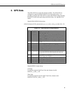
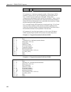
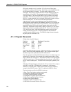
Wiring when using RJ45 adapter:
Function Color Datalogger Connection
Power in Blue 12 volts
Power ground Orange Ground
Power switch Black ground
TXD Green C5
PPS Yellow C8
The GPS16-HVS should be setup for 1200 baud, 8 data bits, 1 stop bit and no
parity. The GPGGA string should be output. The 1 pulse per second signal
should be output with a pulse duration of 80 milliseconds.
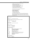
The code required to read the GPS information and store it to final storage is in
Subroutine 98. Subroutine 98 is interrupt driven and triggered when a rising
edge is detected on Control port 8. The GPS16-HVS has a 1 PPS signal which
is wired to control port 8. The transmit data line of serial port 1 on the GPS16-
HVS is wired to control port 5. The GPS16-HVS serial port 2 generally is not
used.
When the 1 PPS signal triggers subroutine 98, P15 is executed. P15 is setup to
read ASCII serial data. Each data point is separated by a non-numeric
character or a decimal point. Fifteen input locations are used as temporary
storage for the $GPGGA string. Table 3.1 explains the $GPGGA string.
The input locations used for the $GPGGA string are:
1) Raw_Time, Time in hours, minutes, and seconds
2) LatDegMin, Latitude degrees and minutes
3) Lat_Frac, Latitude fractions of minute
4) LngDegMin, Longitude degrees and minutes
5) Lng_Frac, Longitude fractions of minute
6) Quality, GPS quality indicator
7) NumSats, Number of satellites in use
8) HDPWhole, Horizontal Dilution of Precision
A-4