


GPS16-HVS GPS Receiver
9
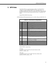
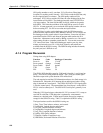
CallTable GGA
CallTable Parsed
NextScan
SerialClose (com1)
EndProg
5. Troubleshooting
Testing and evaluation of serial communications is best done by reducing the
whole system to small manageable systems. Usually some portions of the
whole system are working. The first steps involve finding what is working.
During this process you may find parts of the system that are not working or
mistakes that can be easily corrected. Fix each subsystem before testing
others.
5.1 GPS Setup and Function
Test the GPS16-HVS for proper operation including the baud rate and output
string. Use a computer, terminal emulator software, a serial port (RS232), and
a 9-pin to 9-pin serial cable. The computer and serial port can be the same as
used to communicate with the datalogger. Terminal emulation software is
pretty common. Hyperterm is supplied as part of Windows ™ and works.
Procomm ™ is another communication software package that works well.
Set up the software for the correct serial port, 1200 baud, 8 data bits, 1 stop bit
and no parity. Flow control should be off. Using the serial cable, connect the
GPS16-HVS to the computer serial port. Power up the GPS16-HVS. The
GPS antenna should have a clear view of the sky. Don’t expect the GPS
antenna to work indoors. The $GPGGA string should be displayed once a
second. Make sure the $GPGGA string is showing a valid GPS fix. A valid
GPS fix will display time, position and have a GPS quality number greater
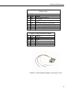
than zero. Part number L17218, RJ45 to DB9 adapter, is needed to connect the
GPS16-HVS to the computer serial cable.