


8
Installation
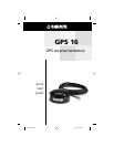
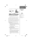
Mounting the
GPS 16
Wiring the GPS 16
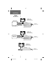
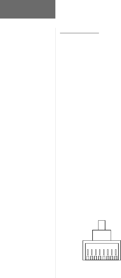
The fi nal step in installing the GPS 16 is to
connect the receiver’s Port 1 DATA IN, DATA OUT,
REMOTE ON/OFF and GROUND (Return) lines to your
NMEA 0183 device or PC. Port 2 is used for RTCM
input only. The GPS 16 may be plugged directly into a
RJ-45 receptacle, which accepts NMEA 0183 data. It is
recommended that a 1-amp, slow blow fuse be installed
on the power (+) line of the receiving RJ-45 receptacle or
equivalent device. Color coding of the wires is the same
on all GPS 16 models (see wiring diagrams on following
pages). If necessary, the wire coloring on the GPS 16 may
be seen through the clear RJ-45 connector.
For reliable communication, it is essential that the
GPS 16 and the receiving device share the same ground.
This ground connection acts as the (signal) return line.
It is recommended to wire the unit to its own circuit to
avoid interference from other electronics.
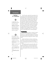
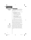
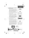
Wire Coloring:
1. RED- Power (+)
2. BLACK- Ground (Power (-) and Data Signal Return)
3. YELLOW- Remote power On/Off (Pull low for ON)
4. BLUE- Port 1 NMEA 0183 or GRMN Data Input
5. WHITE- Port 1 NMEA 0183 or GRMN Data Output
6. GRAY- Pulse Per Second Output (See Tech Specifi cations)
7. GREEN- Port 2 RTCM SC-104 Differential Data Input
8. VIOLET- Port 2 Data Output (Reserved for Future Use)
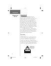
GPS 16
RJ-45 Connecto
r
(Cable View)
2
1
367485
GPS16 QSG.indd 1/7/02, 4:08 PM8