


10
11
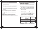
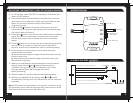
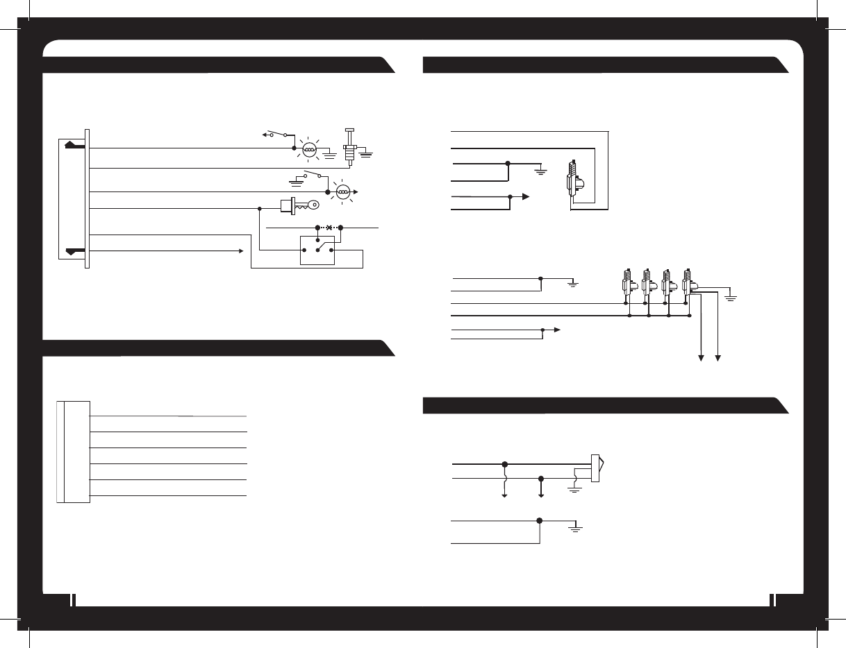
6. Red/White Wire: (-) 200mA Programmable Output
2. Blue Wire: Instant Trigger Ground Input
1. Violet Wire: Positive Door Pin Switch Input
4. Yellow Wire: To Ignition Switched + 12V
5. Orange Wire: 200mA Grounded when armed
3. Green Wire: Negative Door Pin Switch Input
85
86
30
87a
Cut
To startsolenoid
From ignition switch
Red wire
White wire
Orange
wire
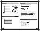
Channel 3 / 2Step Door Unlock.
12V
12V
Y
ellow wire
Blue/White
Wire:
(30
)-DoorUnlockRelay
Blue/Red
Wire:
(87a )
- Door Unlock Relay
Blue/Yellow
Wire:
(87)
- Door Unlock Relay
Green/Red
Wire:
(87a)
-Door LockRelay
Green/White
Wire:
(30
)-DoorLockRelay
Green/Yellow
Wire:
(87)
-DoorLockRelay
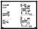
+12V
Green/wh ite
Blue/white
Blue/red
Green/red
Green/ye llow
Blue/yellow
+12V
Green/white
Blue/white
Blue/red
Green/red
Green/yellow
Blue/yellow
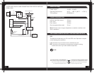
To Door
UnlockControl
Wire
To Door
LockControl
Wire
Blue/white
Green/white
Door Lock
Master
Locking
Switch
Door unlock
Green/yellow
Blue/yellow
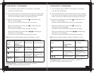
A: CENTRAL LOCKING DIAGRAMS
B: CENTRAL LOCKING DIAGRAMS
INSTALLING DOOR LOCK MOTORS (2 WIRE)
INSTALLING 4 DOOR LOCK MOTORS (WITH 5-WIRE LOCK MOTOR)
NEGATIVE TRIGGER DOOR LOCK SYSTEM
B: 6 PIN MINI CONNECTOR WIRE HARNESS:
C: 6PIN DOOR LOCK/UNLOCK WIRE HARNESS:
(See central locking diagrams)
(After market Door Motors)
(Factory Door Locking System)