Sales • Service • Recycling 1-888-563-6300
3
2. INTRODUCTION
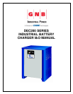
The GNB® DEC200 battery chargers are fan cooled, solid state, microprocessor
controlled, SCR regulated chargers designed to make battery charging simple. They
are designed to charge flooded lead-acid batteries. The charger has a
comprehensive self-checking diagnostic program to control all charger functions,
monitor the quality of charge and check its own safety conditions.
3. RECEIVING CHARGER
Examine the charger thoroughly before using, to make sure that no parts have been
loosened or damaged during shipment. Check the contents of the package against
the delivery slip before disposing of the shipping package. If any shipping damage or
partial loss is found, file a claim with the carrier without delay and take any necessary
steps to protect your rights. Before installing, check that the charger nameplate data
corresponds to the packing slip and to the model specified on the original sales
order. The DEC200 chargers are delivered on skids for easy handling using a forklift
truck.
4. LOCATION AND INSTALLATION OF CHARGER
Proper installation is important in order to achieve good charger performance and
long trouble free operation and to prevent damage to the charger and batteries. The
charger should be located in a clean, cool, normal ambient room temperature
(between +32
o
F/0
o
C and 104
o
F/40
o
C), dry and well-ventilated area. In order to permit
free air flow for convection cooling allow four inches minimum between the charger
and any wall, six inches from other equipment, and never store anything beneath or
on top of the charger.
5. STACKING
The following recommendations should be taken into consideration when stacking
these units:
a) The base unit should be secured to the floor or a solid base using appropriate
bolts and with accordance to local building codes and regulations.
b) These units can be stacked to a maximum 3 high.
c) If a lifting sling is used, the sling should be placed under the unit where the base
plate is located to avoid damage to the units.
Lifting Sequence is as follows: -
a) Secure the base unit to the floor or solid base. The bolts can be accessed and
secured from the underside of the unit at the front and rear or from inside the unit
where the large holes are located directly above mounting holes (see appendix G
for mounting hole locations). When accessing the mounting holes from the
inside, it is recommended you use a long handle hexagon key or screwdriver with
the hexagon key inserted. This will allow you to go through the base plate to the
bolts, which are located on the flange.


