


APPENDIX D
OR
bl
gy
bl
br
PCB1
bk
rd
bl
wh
wh
wh
Shunt
bl
gy
+
_
bl
FS2
wh
rd
wh
bl
rd
rd
bk
Component No:
CLT6005
DRAWING TITLE:
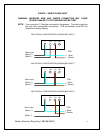
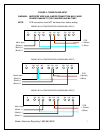
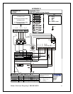
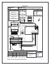
GNB [UL] Single phase wiring diagram Fuse / Breakers
CON 5
12345678
CON1
FS1
1234
YL/G
KEY
bl BLUE
bk BLACK
br BROWN
gy GREY
rd RED
wh WHITE
YL/G YELLOW / GREEN
L
N
N
L
OR
OR
L
N
If any errors are apparent within this
diagram please inform CMP
engineering.
CMP Batteries Ltd,
Charger Division,
Unit 2 Pisces,
Mosley Road,
Trafford Park,
Manchester.
M17 1PF.
DRAWING No: 4 - CMP - 2600 - 02 - WD - E
Drawn by:
Trev Peacock
Checked by:
MOD No: REV:
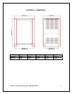
Materials: White Polypropylene 60u PP198 TC
Clear Overlaminate 60u PP20
Adheasive: AP51
Size: A5 (210mm x 147mm)
Text: As shown
Colour: Black on white
C000007
B
-
Trev Peacock
Trev Peacock
10 12 03
17 03 04
17 04 03
-
C000044
C
Trev Peacock
19 12 03
-
C000045
D
For 120V input connect to 120V
connections on T1
For 208V input connect to 208V
connections on T1
For 240V input connect to 240V
connections on T1
For 480V input connect to 480V
connections on T1
br
0
V
-
C000068
E
0
V
2
0
8
V
2
4
0
V
4
8
0
V
0
V
2
4
0
V
1
2
0
V
T1
2
0
8
V
240V
Sales • Service • Recycling 1-888-563-6300
17