


_l[-_i_[Ltl/:l_:]ljllllHl_|;lill:lz_;_il[O]Z_ id::_"]ld::lZ_
This battery charger has a built-in alter-
nator tester that dispIays either an accu-
rate alternator voltage or an estimate of
the alternator's relative output compared
to normal alternators. The Alternator %
values displayed should be taken as
general reference, not precise diagnosis.
The alternator tester functions the same
as the battery tester (see previous sec-
tion of this manual for details) with a few
differences.
TESTING SEQUENCE
There are three basic steps required to
use the 71227 as an alternator tester.
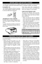
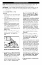
1. Connect the charger battery clamps to
the battery or charging system. Be sure
to follow all of the precautions listed
under "OPERATING INSTRUCTIONS".
2. Connect the charger power cord to a
129V AC 2-prong wall outlet. Again, be
sure to foIIow all of the precautions listed
under "OPERATING INSTRUCTIONS".
3. Start the vehicle and turn on the
vehicle's headlights. Read the voltage
on the digital dispIay or press the
DISPLAY MODE button to set the
tester to ALTERNATOR % and read
the alternator percent.
TESTER STATUS LEDs
When the 71227 is operating as an alter-
nator tester, the status LEDs light under
the following conditions.
• The CHARGED (green) LED will light
if the output of the charging system is
at the normally desired level.
• The CHARGING (yellow) LED does
not light in the alternator test mode.
• The CHECK (red) LED lights if the
VOLTAGE is much higher or lower
than normally desired.
• When the tester display mode is set
to VOLTAGE, the CHARGED and
CHARGING LEDs won't light (it could
be testing a battery or an alternator).
ALTERNATOR TESTING NOTES
• The alternator percent display can
range from 0 to 199.
• The DISPLAY MODE cannot be setto
ALTERNATOR % during charging.
t2