


©2002 Edelbrock Corporation
Rev. 9/02
Brochure No. 63-0142
Catalog #71001
Page 12 of 21
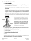
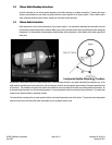
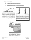
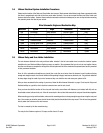
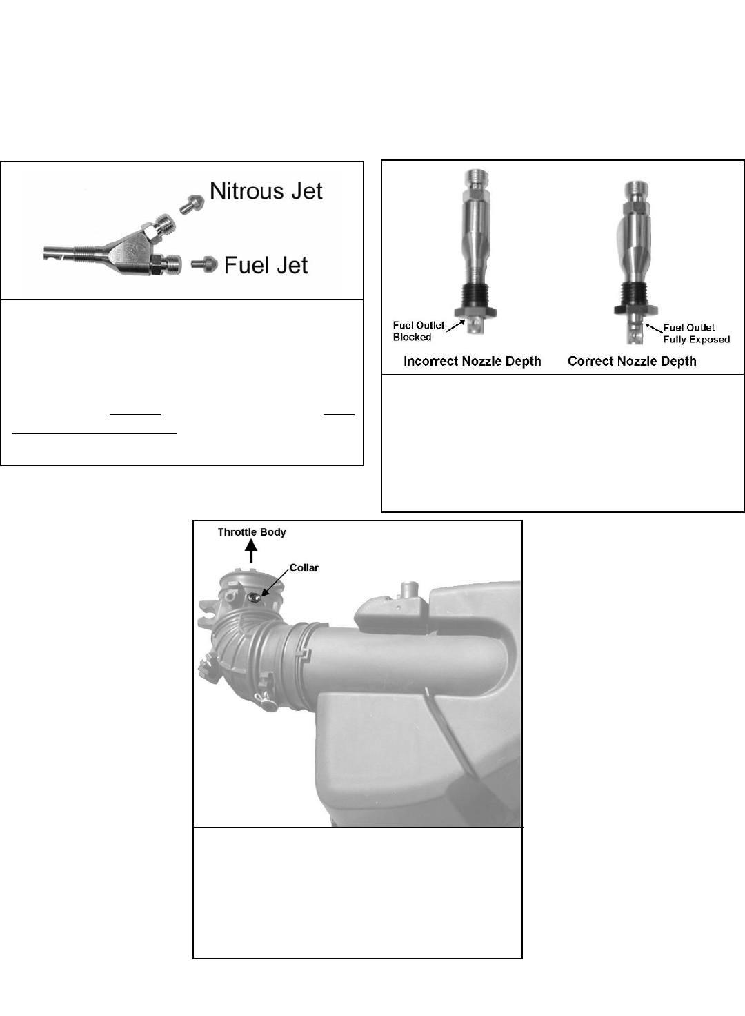
Shown above is the correct and incorrect nozzle depth. Be certain
that the nozzle protrudes as shown to prevent severe engine
damage. If the nozzle does not protrude far enough, the fuel outlet
will be blocked, causing an extreme lean condition in the engine
which would cause a catastrophic engine failure. If the depth in
incorrect, use the supplied 1/16”NPT tap to acheive the correct
depth.
2.7 Nozzle Installation (Continued)
8. Using liquid Teflon, install the nozzle into mounting collar.
9. Be sure the nozzle discharge is towards the vehicles engine.f the nozzle.
10. Install the correct jets into the fuel and nitrous inlet fittings of the nozzle. Please refer to Section 1.2 Jet Map
Information to determine the correct nitrous and fuel jets to install into the nozzle.
11. Install 3AN lines from solenoid outlet fitting to spray nozzle jet fittings and tighten securely.
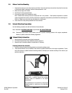
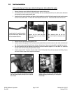
12. Install the intake boot.
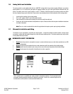
Nozzle should be placed in the intake boot so as to have a
clear path to the throttle body. Try to keep the nozzle from
having to travel through the bend in the intake boot and as
close to the throttle body as possible. Shown to the right is
an installed collar and nut in the stock intake boot of an
Acura RSX.
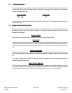
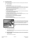
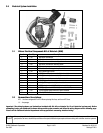
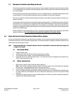
Shown above is the nozzle depicted with the appropriate jets.
Nitrous and fuel jets are similar in appearance except for the
difference in their orifice sizes which is stamped on the jet body.
When installing the nitrous and fuel jets supplied with your system,
be certain that you install the correct jet into the correct nozzle inlet.
By installing the incorrect jets into the nozzle inlets, severe
engine damage would occur. Please refer to Section 1.2 Jet
Map Information for the correct jets to install in your nozzle.