©2007 Edelbrock Corporation
Brochure #63-0478
Catalog #70410
Rev. 7/07 - DC/mc
Page 12 of 16
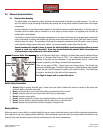
3.5 Wiring
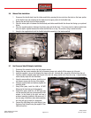
1. Verify that the battery is disconnected. If it is not, remove the ground strap and place it away from the battery to keep it
from shorting out.
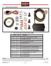
2. Locate the red wire with fuse holder and affix it to the red wire on the “WOT” module with the provided butt connector or
you can solder the two ends and then heat shrink, if so desired (required soldering iron, rosin core solder and heat shrink
not provided in kit).
Note: You may need to cut the red wire coming out of the “WOT” module wiring harness to accommodate the mounting
location and proximity to the battery.
3. Connect the Red wire with fuse holder to the Positive terminal of the car battery.
4. Locate the Black wire on the “WOT” harness. Affix the Black wire with ring terminal to a good chassis ground. We
recommend using an existing ground used by the OEM.
5. Locate the Yellow wire coming out of the “WOT” harness. Using provided male and female spade connectors, attach the
yellow wire to one black wire from each of your solenoids.
6. Locate the remaining black wire on each of the solenoids. Using provided ring terminal, affix the black wires to a good
chassis ground.
See Step 4.
7. Locate the Blue wire on the “WOT” module. With provided female spade connector, attach blue wire to one of the terminal
of the on/off rocker switch.
Note: Wire length might need to be extended depending on the location of the “WOT” module.
8. Attach Blue wire extension to free terminal of on/off toggle switch.
9. Locate the Yellow/White wire running from the throttle position sensor to terminal #61 of ECM wiring harness connection.
10. Affix Blue wire from on/off rocker switch to Yellow/white wire from throttle position sensor with provided splice connector.
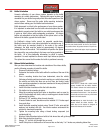
3.6 Arming Switch and Installation
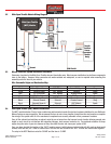
The arming switch is a Black, non-illuminated switch that is a “MASTER” arming switch for your nitrous system. Without it, your
nitrous system would be “on” all of the time and capable of engaging anytime you go to wide-open throttle conditions with your
vehicle. The Switch is marked to indicate when it is in the “on” and the “off” position Therefore, it should be placed in an obvious
position well within the line of sight and easy reach of the driver. Please refer to the procedures below for the installation of the
arming switch:
1. Locate the final position of your arming switch.
2. Using a uni bit or 13/16 drill, drill a hole for the switch location.
Note: If using a uni bit, try to drill the hole slightly under 13/16” diameter for a snug fit.
3. Insert the switch from in front of the mounting hole, it should lock in place.
4. Do not wire until all other mechanical components are in place. Please see the electrical system installation instructions
for further information.
3.7 Final Solenoid and WOT Module Installation Recommendations
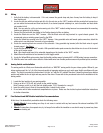
At this time, it is advised that you double-check the following areas:
1.
Double Check
all wires making sure they do not come in contact with any heat sources like exhaust manifolds, EGR
crossover, etc.
2.
Check
all connections for exposed wire, try to keep all wire within the insulation or use shrink wrap to prevent any loose
wires from shorting out.


