


©2002 Edelbrock Corporation
Brochure No. 63-0029
Rev. 12/02
Page 21 of 26
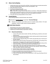
4.5 Voltage Booster Unit Relay Installation
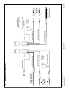
The Voltage Booster Unit Relays need to be mounted in the trunk of the vehicle within range of the fuel pump wiring
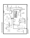
harness. Please refer to the wiring schematic on page 18 for assistance is determining the origin and destination
of each wire. Determine a location in the trunk compartment that you can solidly mount the 2 relay harnesses. Be
sure that all of the wires will reach their given destinations before mounting the relays permanently. We recommend
that you mount the relays side by side and mark then “1” being the left relay and “2” being the right relay. For the
remainder of the relay wiring instructions, we will be referring to the relays as relay 1 and relay 2 to simplify the
installation.
1. Remove the floor carpet from the trunk and set aside.
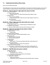
2. Locate the factory fuel pump wire harness. This should be located to the right of the spare tire compartment.
The harness will consist of several wires bound together and covered with plastic tubing. Pull back the tubing
to give access to the individual wires.
2. Locate the brown wire with the pink stripe in the harness. Cut this wire several inches back from the plastic
bulkhead which leads down to the fuel pump. Terminate the end of the wire that travels into the plastic
bulkhead with a male spade connector.
3. Locate the red fused wire on relay 1. Terminate the end of this wire with one of the supplied female spade
connectors and connect this terminal to the male spade on the pink/brown wire.
4. Terminate the remaining pink/brown wire with a female spade connector. Terminate the green wire from relay
1 with one of the supplied male spades and connect to the female spade terminal of the pink/brown wire.
5. Locate the black wire with a red stripe in the harness. Cut this wire several inches back from the plastic
bulkhead which leads down to the fuel pump. Terminate the end of the wire that travels into the plastic
bulkhead with one of the supplied female spade connectors.
6. Locate the red fused wire on relay 2. Terminate the end of this wire with one of the supplied male spade
connectors. Connect this terminal to the female spade connector on the red/black wire.
7. Terminate the remaining red/black wire with the remaining male spade connector.
8. Locate the green wire from relay 2 and terminate the end of the wire with the remaining female spade
connector. Connect this terminal to the male spade on the red/black wire.
9. Using one of the supplied butt connectors, connect the blue wire on relay 1 to the red positive output wire from
the voltage booster unit.
10. Using the remaining butt connector, connect the blue wire from relay 2 to the black ground wire from the
voltage booster unit.
11. Terminate the black ground wire from relay 1 with the supplied 3/8” ring terminal. Connect the ring terminal
to a chassis ground.
12. Route the white wire on relay 2 through the passenger compartment to the toggle switch. Using the supplied
splice connector, splice this wire in line with the “On Acc.” wire coming from the toggle switch.
13. Connect the orange 12 volt power wire from the Voltage Booster Unit to the battery.
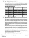
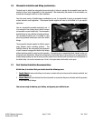
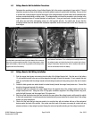
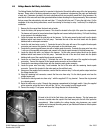
Pictured to the left is the Ford factory fuel pump wire harness. This fuel pump wire
harness is located under the carpet in the trunk area just to the left of the spare tire
compartment. When installing the voltage booster relay harnesses, pay careful
attention not to intercept the wrong wires or your Edelbrock Performer nitrous system
will not work properly.