


©2002 Edelbrock Corporation
Brochure No. 63-0029
Rev. 12/02
Page 20 of 26
4.3 Voltage Booster Unit Installation Procedures
Determine the mounting location of your Voltage Booster Unit in the engine compartment of your vehicle. This unit
should be mounted as close to the battery as possible without coming in contact with the battery. Be sure to find
a location that is solid enough to support the weight of the voltage booster unit when under harsh conditions such
as heavy acceleration/braking or bumpy roads. The voltage booster unit should be mounted in a dry location in the
engine compartment since it is water-resistant, not water-proof. Once you have found a location, mount the unit
with either nuts and bolts, self-tapping screws, etc. (Not supplied with kit). You should also be sure that the
mounting location does not interfere with mechanical operations under the hood such as the hood clearance or
hood hinges.
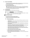
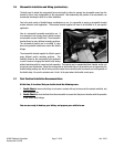
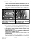
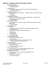
Above is a picture showing the Voltage Booster Unit placement in
our Edelbrock Test Vehicle. This is the optimal mounting location for
the voltage booster unit under the hood of the vehicle due to there
being to mechanical devices for the unit to interfere with and the
unit can be mounted next to the battery.
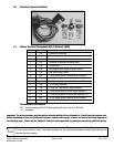
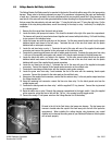
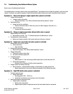
Above is a picture showing the Voltage Booster Unit up close. Be
sure that when you mount the unit, you bolt down all four corners of
the unit to a secure mounting location. Be sure that you are in close
reach of the battery. Also, be sure to ground the unit directly to the
negative terminal of the battery.
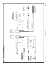
4.4 Voltage Booster Unit Wiring Installation
1. Find the orange fused power wire coming from the side of the Voltage Booster Unit. Run this wire to the battery
12-volt positive terminal to be sure you have adequate line length to reach the terminal. Do not connect this wire
until you are finished with the voltage booster unit and voltage booster unit relay wiring, due to the risk of electric
shock.
2. Locate the black ground wire which should be located directly beside the orange fused power wire. Connect this
directly to the ground terminal of the battery.
3. Locate the light blue activation wire which should be on the opposite side of the voltage booster unit from the
orange fused power wire. Using one of the 16/18g splice connectors supplied in the voltage booster relay pack,
splice the light blue wire into the orange fused 12v power wire.
4. Run the red and the black wires which are located on the same side of the voltage booster unit through the vehicle
to the trunk compartment. Leave these ends non-terminated until you are instructed to connect them in the voltage
booster unit relay instructions.
5. Check all of the wires that you have just routed to be sure that they will not interfere with any of the mechanical
devices under the hood of the vehicle. Also, make sure that none of the wires are coming in contact with any
abrasive surfaces or sharp edges to prevent fraying the wires and possibly shorting out the voltage booster unit.