


©2003 Edelbrock Corporation
Brochure No. 63-0173
Rev. 02/03
Page 12 of 23
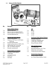
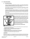
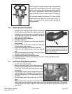
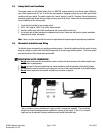
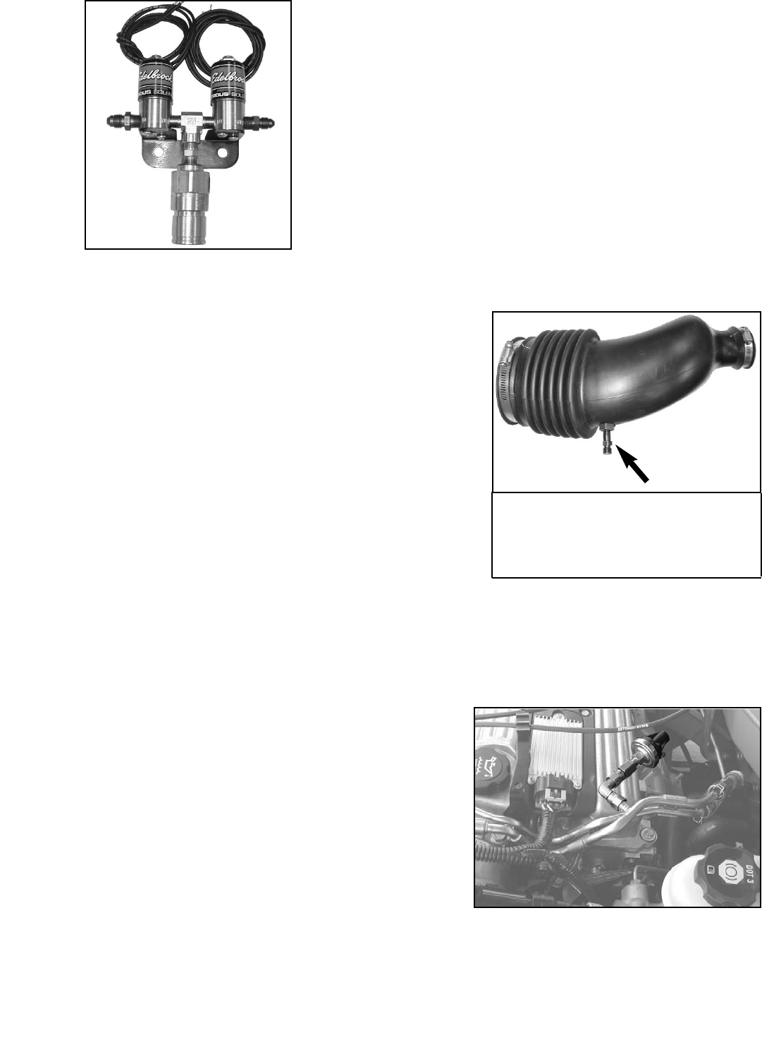
Here is a typical EFI solenoid assembly using an unmodified EFI
solenoid bracket. Modifications performed to a solenoid bracket
depend on many factors. When mounting the solenoid assembly
on a vehicle, considerations should be taken regarding any
potential interference with the vehicle’s systems or components.
The line length between the Performer 2.2L Ecotec solenoid
assembly and the jet fitting on the nitrous spray nozzle is 24
inches. This should also be considered when mounting the
solenoid assembly.
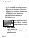
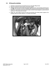
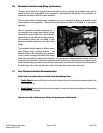
2.6 Nitrous Spray Nozzle Installation
1. Determine nozzle mounting location in intake boot, between
the MAF sensor and the throttle body. Make sure the nozzle,
mounting collar, and the feed line from solenoid to nozzle, do
not interfere with any systems or components of the vehicle
such as the hood latching device.
2. Mark where the nozzle will be placed.
3. Remove the intake boot.
4. Drill a 7/16” hole in the intake boot where nozzle placement
was determined.
5. Be sure to clean out the rubber shavings you made when
drilling to prevent engine damage.
6. Install nozzle mounting nut and collar onto intake boot.
7. Using liquid Teflon, install the spray nozzle into mounting
collar.
8. Mark the spray direction on the nozzle. Be sure the nozzle
discharge is towards the vehicles engine.
9. Install the correct nitrous jet into the nozzle fitting.
10. Install the 3AN line from solenoid outlet fitting to spray nozzle jet fitting and tighten securely.
11. Install the intake boot.
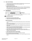
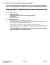
2.7 Fuel Pressure Safety Switch Installation
1. Locate the fuel rail test port fitting.
2. Make sure the vehicle’s engine is cool. Release pressure in
the fuel system by pressing down on the valve in the center
of the fitting. This will allow the pressure to escape as well
as some fuel.
3. After relieving all pressure, remove test port fitting core and
install the 4AN female to 4AN male 90° fitting onto the rail.
4. Install the 4AN female to 1/8”NPT female fitting onto the
90° fitting.
5. Install the 50psi Hobbs Safety Switch into the 1/8”NPT
fitting.
Note: On some vehicles, there is no test port fitting, or the
location of the test port fitting does not allow ample room for the fuel pressure safety switch to be mounted.
These applications will require a “Banjo Nut” at the fuel filter to be drilled and tapped to allow mounting of the
safety switch.
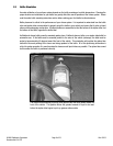
Nozzle should be placed in the intake boot so as
to have a clear path to the throttle body. Try to
keep the nozzle from having to travel through the
bend in the intake boot and as close to the
throttle body as possible.