


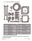
Catalog #70080, #70081, #70082, #70083
Brochure No. 63-0312
©2008 Edelbrock Corporation
Rev. 07/08
Page 6
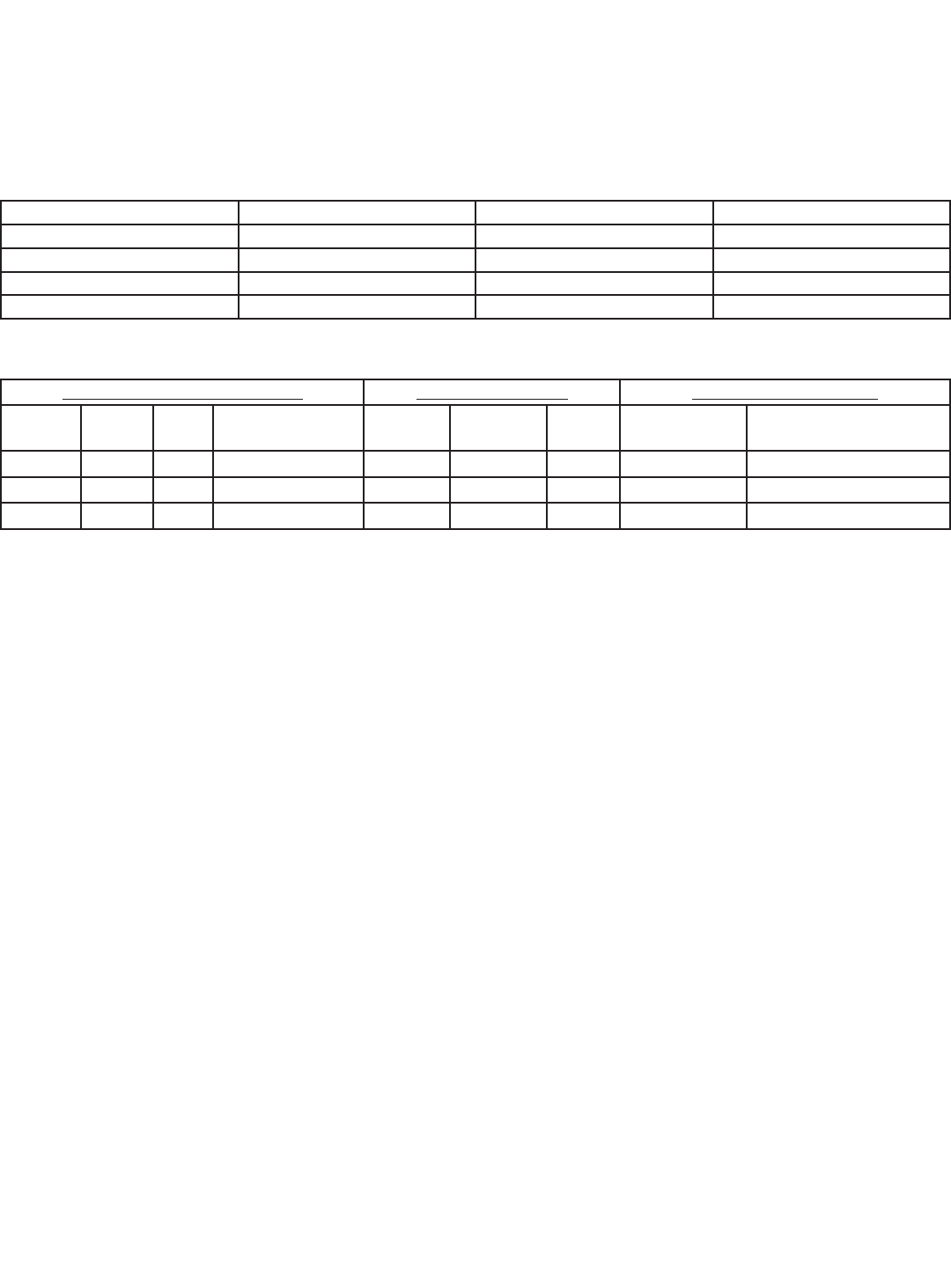
1.2 Jet Map Information
Edelbrock engineering has conducted dyno testing with the Performer RPM II system to provide you with a baseline jet
map. These jet combinations are supplied with this system to enable you to vary your engine’s power output. On a typical
mildly to highly modified 350 or larger cubic inch engine, you can expect the following approximate power gains for each
of the jetting levels:
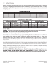
Performer RPM II Jet Map
2-Stage Performer RPM II Jet Map
JET MAP NOTES:
Pressures: Maintain 6.5 psi fuel pressure and 950 psi nitrous oxide bottle pressure for safe and effective operation.
Spark Plugs: Two heat ranges colder than an equivalent naturally aspirated engine would use.
Fuel: 110 octane or higher race gas is required to prevent detonation.
The dyno tests were conducted at Edelbrock using a highly modified Big Block Chevrolet. Modifications included Edelbrock
intake manifold, cylinder heads dyno headers, pistons, rods, crankshaft, and improved ignition. All stated timing
adjustments listed in the jet map are where the motor being tested performed best. Final timing should be adjusted to
achieve best power and/or MPH per application.
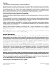
See section “5.0 Ignition Timing and Nitrous” for more information on
timing selection.
Any variations in jetting patterns other than what is listed above and engine damage could occur. Please contact Edelbrock
Technical Department with any questions you have concerning jetting patterns and their effects on engine performance.
Edelbrock recommends an NGK spark plug with a heat range between -9 and -11, depending on the power level being
used. When in doubt, always go to the next cooler heat range.
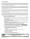
The Performer RPM II Series Nitrous Systems are intended for single-plane manifolds only. Do not use a
dual-plane manifold with the Performer RPM II Series Nitrous Systems. In testing, we found that dual-plane
manifolds have some distribution problems at these super high flow rates that could cause serious engine damage.
Approximate HP Gain Nitrous Jet Fuel Jet Timing Adjustment
200 85 85 7°-9° retard
225 93 93 8°-10° retard
300 102 102 11°-13° retard
400 116 116 15°-17° retard
1st Stage Jet and Timing Map 2nd Stage Jet Map Dual Stage Timing Map
Initial HP
Gain
Nitrous
Jet
Fuel
Jet
1st Stage Timing
Adjustment
Additional
HP Gain
Nitrous Jet Fuel Jet Total HP Gain Total Timing Adjustment
100 59 59 3°-5° retard 100 59 59 200 7°-9° retard
150 71 71 5°-7° retard 150 71 71 300 11°-13° retard
200 85 85 7°-9° retard 200 85 85 400 15°-17° retard