


Catalog #70080, #70081, #70082, #70083
Brochure No. 63-0312
©2008 Edelbrock Corporation
Rev. 07/08
Page 20
Fuse
Holder
2nd
Stage
Relay
1st
Stage
Relay
Battery
Red
Blue
Red
White
Black
Black
Blue
Ground
Ground
Ground
Ground
White
1st
Stage
Solenoid
1st
Stage
Solenoid
2nd
Stage
Solenoid
2nd
Stage
Solenoid
Black
Switched
+12V
Microswitch
Pushbutton
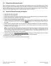
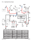
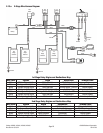
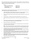
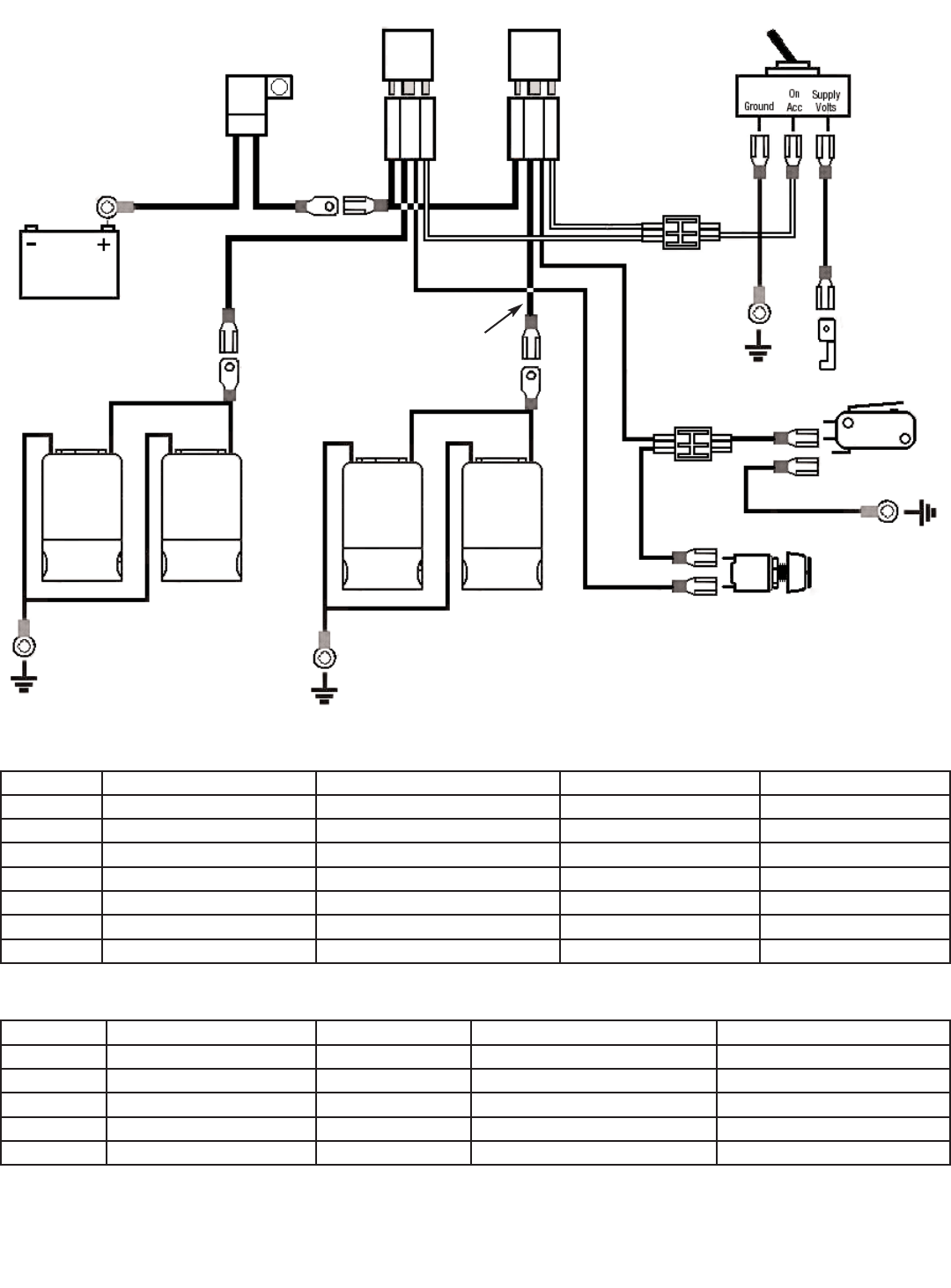
2.13.a 2-Stage Wire Harness Diagram
Wire Color System Origin Destination Terminal Used
Red Main voltage supply Relay harness +12V Battery terminal Ring
Blue 1st stage solenoid power Relay harness Solenoid wires Male/Female spade
White System arming signal Relay harness Arming switch “ON ACC” Female spade
Black Arming switch power Arming switch “ground” Ground Female spade/ring
Red Arming switch power Arming switch “Supply Volts” Switched +12V Female spade
Black System arming signal Relay harness Microswitch Female spade
Black 1st stage trigger signal Microswitch Ground Female spade/ring
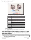
1st Stage Relay Origins and Destinations Map
Wire Color System Origin Destination Terminal Used
Red Main voltage supply Relay harness +12V Battery terminal Ring or Scotchlok
Blue 2nd stage solenoid power Relay harness Solenoid wires Male/Female spade
White System arming signal Relay harness Arming switch “ON ACC” Female spade or Scotchlok
Black System arming signal Relay harness Pushbutton Female spade
Black 2nd stage trigger signal Pushbutton Microswitch Scotchlok
2nd Stage Relay Origins and Destinations Map