


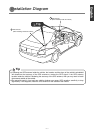
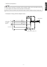
Route the parking brake signal wire to the main
unit.
-
11
-
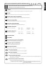
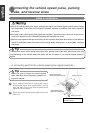
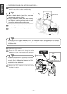
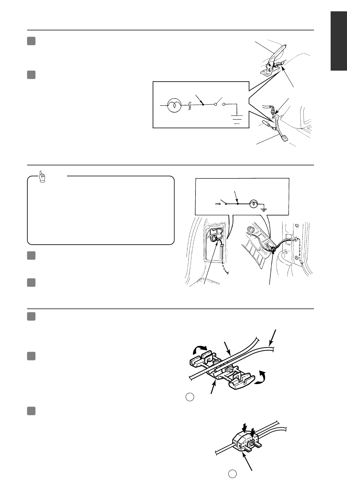
Foot-operated
parking brake
Hand-operated
parking brake
-
A connecting the point for parking brake signal (example)
-
Attach a splicing
connector at this location.
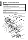
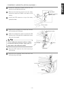
Reverse signal wire
Reverse lamp
Reverse signal wire
-
A connecting point for the reverse signal (example)
-
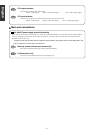
••
Be sure to connect the reverse signal wire. If it is
not connected, the vehicle position may be
incorrect when the vehicle is reversed.
••
Use a circuit tester to confirm that a sensing voltage
of 6 V or higher is generated when the vehicle is
reversed.
Tip
-
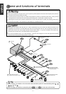
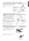
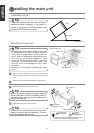
Using the splicing connector
-
Insert the interconnecting wire [vehicle speed
pulse signal wire (purple/white), parking brake
signal wire (red/white), or reverse signal wire
(green)] from the main unit and the vehicle wire
into the splicing connector.
1
Push in the terminal (the metal part) of the
splicing connector using a pair of pliers.
2
Harness in the car
Vehicle speed pulse signal wire
(purple/white), parking brake wire,
(red/white) or reverse wire (green)
Splicing connector
11
Press down the cover of the splicing connector
and squeeze it until it locks.
3
Lock
Splicing connector
11
Use a splicing connector to connect the reverse
signal wire (green) coming from the main unit to
the reverse signal wire of the vehicle.
1
Route the reverse signal wire to the main unit .
2
Use a splicing connector to connect the parking
brake signal wire (red/white) coming from the
main unit to the parking brake signal wire of the
vehicle.
1
2
Parking brake
signal wire
Attach a splicing
connector at this location.
Parking brake
signal wire
Español Français Italiano
Nederlands
SvenskaEnglish